Capstone Design Project
Design Guidelines
Each student in the class was tasked with designing a Fat Tire Trike in 15 weeks
The Fat Tire Trike design guidelines:
Design must use three 12-inch diameter, 8-inch-wide tires
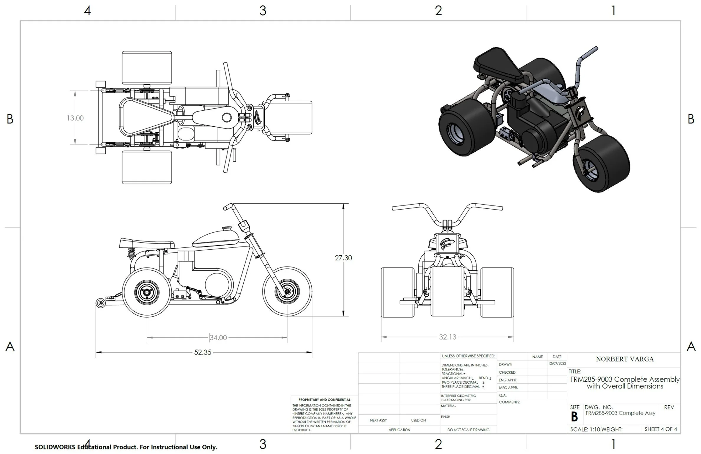
Maximum wheelbase is 34-inches
Maximum width of the trike is 40-inches
Minimum ground clearance is 3-inches
Rear brakes only (hydraulic or mechanical)
Individual tubing pieces limited to 2 bends
Project Overview
Week 1 - Research and initial sketches
Week 2 – Drawings of commercial parts
Week 3 – Fork sub-assembly
Week 4 – Frame sub-assembly
Week 5 – Rear axle and wheelie bar sub-assemblies
Week 6 – Complete frame and detail drawings
Week 7 – Complete assembly drawings
Week 8 – Prototype build
Week 9 – Preliminary bill of materials
Week 10 – Stress analysis
Week 11 – Revised sub-assemblies and full assembly
Week 12 – B.O.M, raw materials list, and purchase orders
Week 13 – Detail drawings of manufactured parts
Week 14 – Manufacturing processes
Week 15 – Project completion
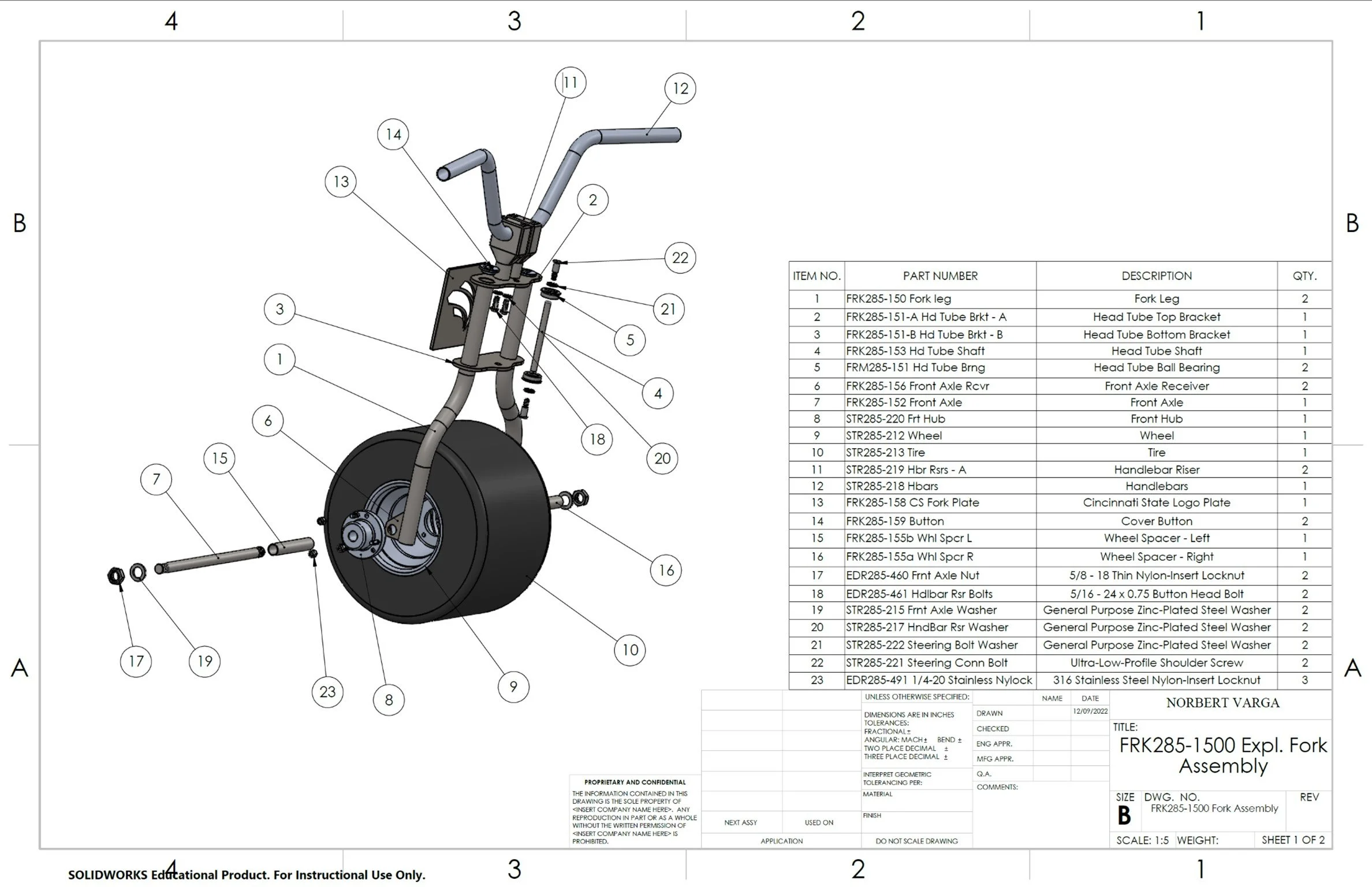
Drawings of Commercial Parts
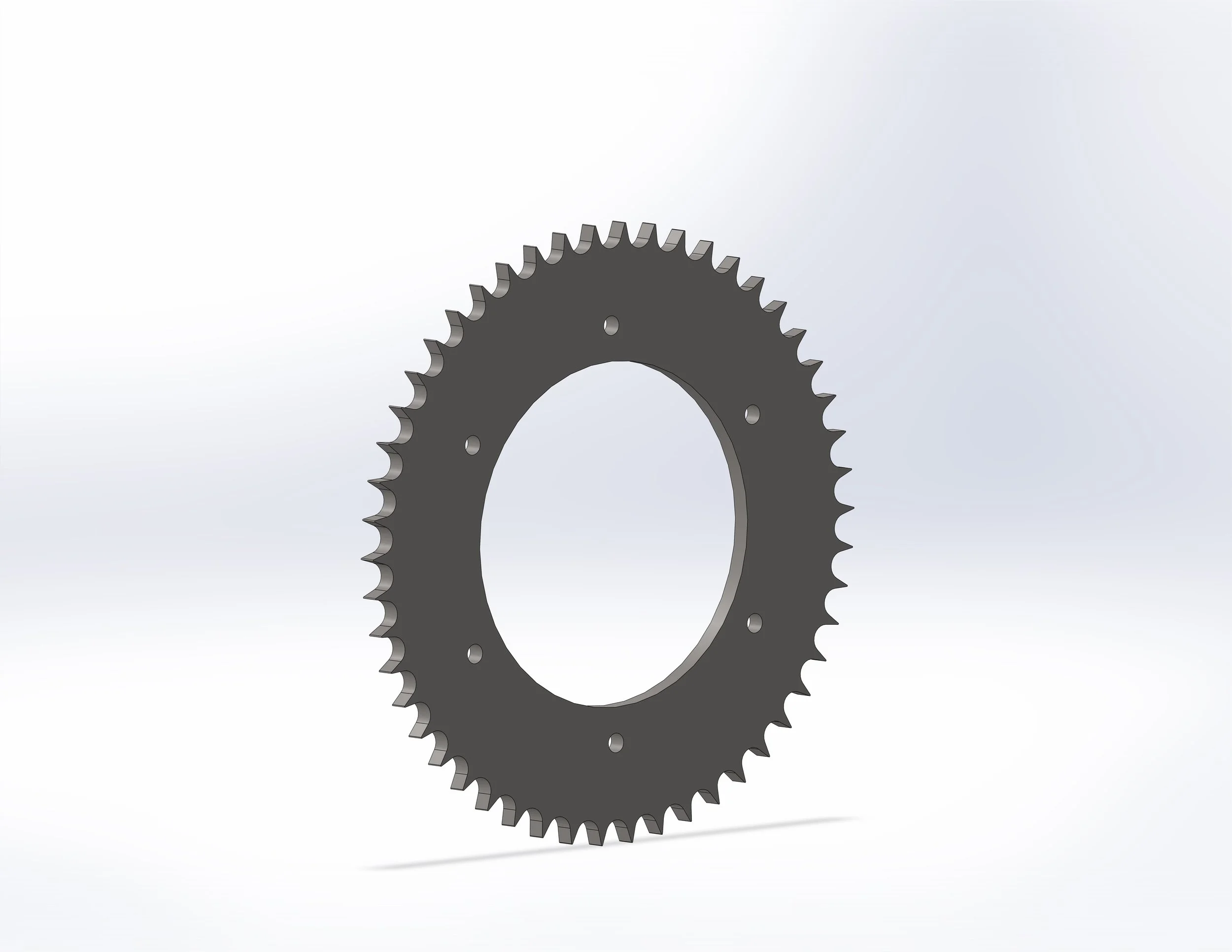
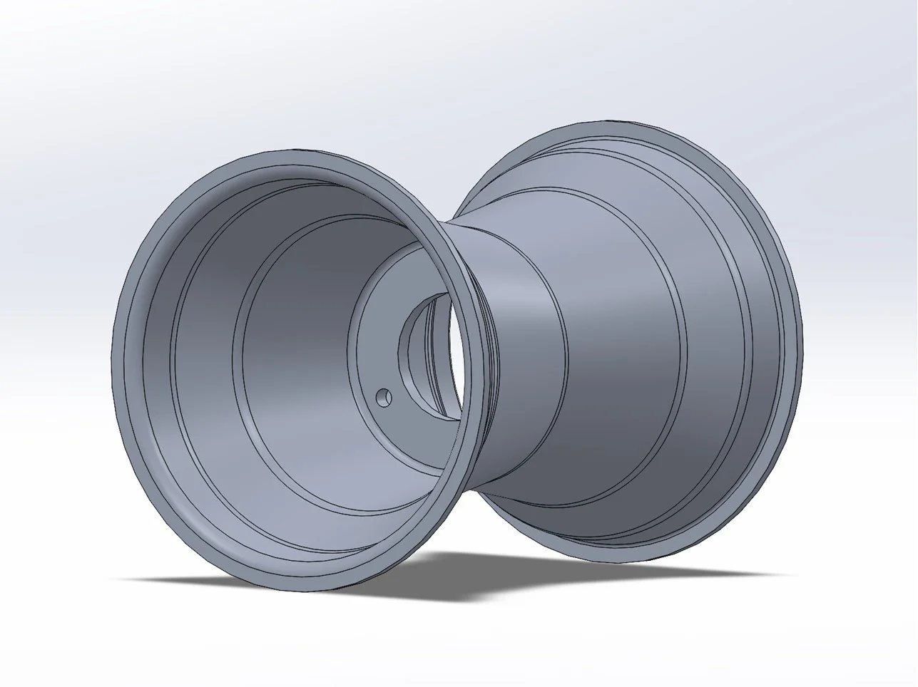
Commercial parts that were going to be purchased for this project were modeled in Solidworks to aid assembly and fitment with the parts that were going to be manufactured.
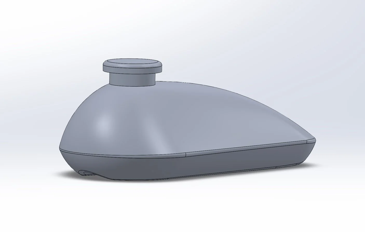
Initial Sketches
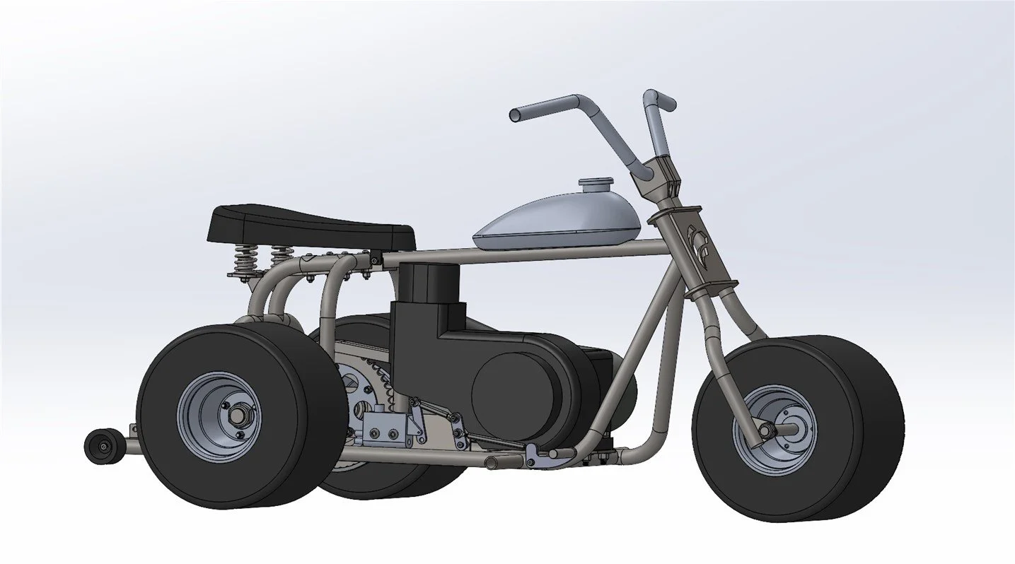
In order to better visualize proportions, as well as allow for easy manipulation of parts, I elected to use the Solidworks CAD software to create my sketches. This decision proved especially helpful when it came to determining the dimensions of the Trike.
Prototype Building
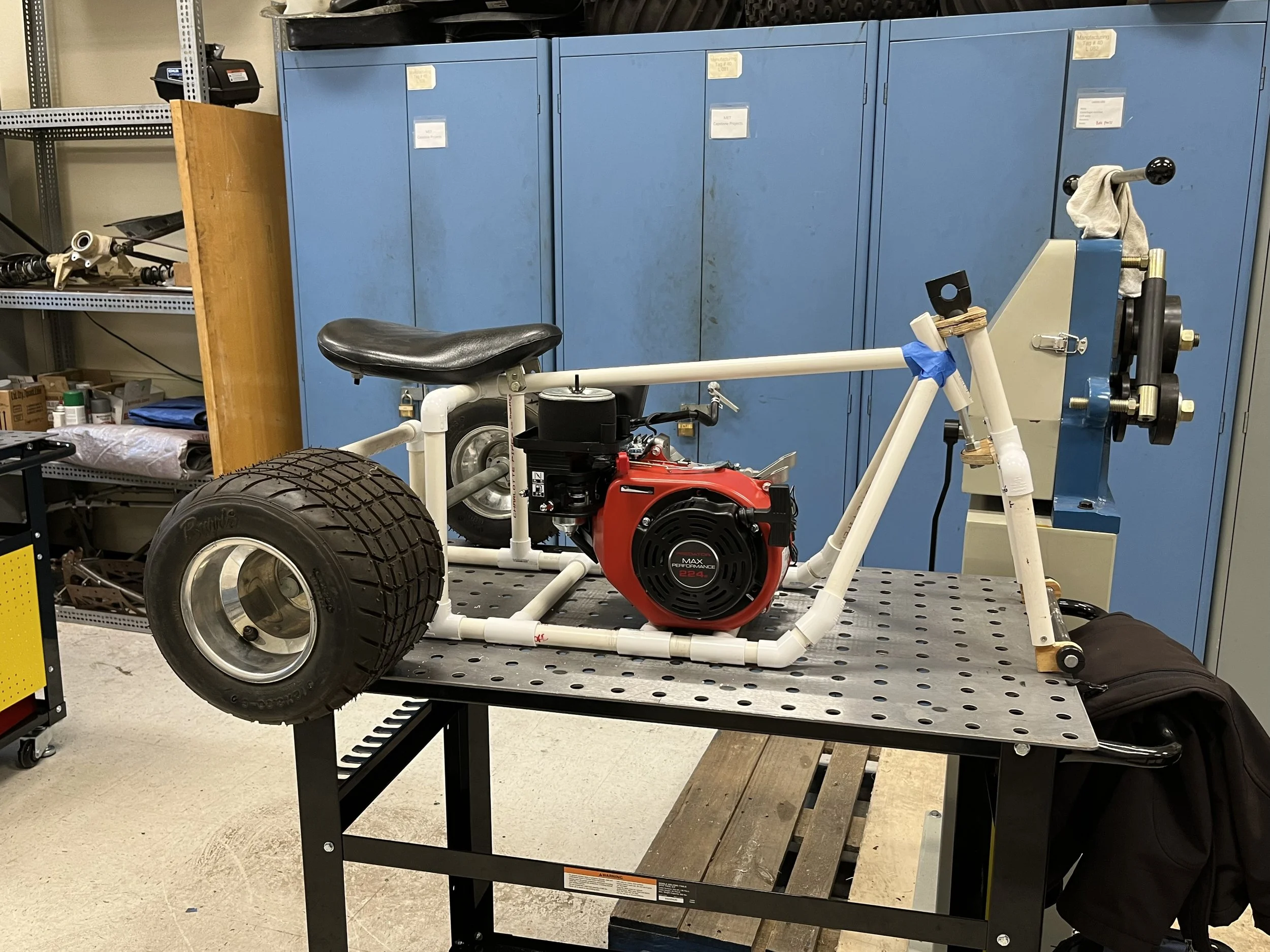
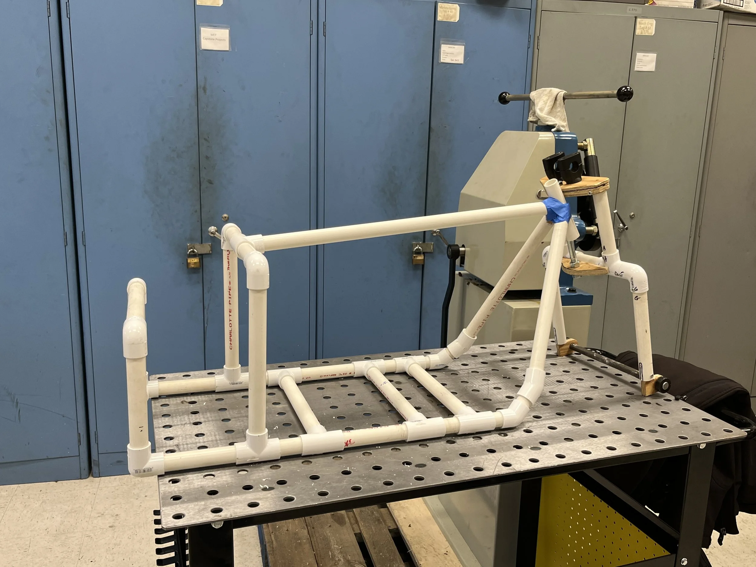
To ensure that the engine and the rear axle assembly will fit as designed, we were tasked with creating a frame prototype out of PVC piping and fittings. The fork assembly was a generic unit supplied by the professor and was not made as part of this project.
Sub-Assembly Drawings
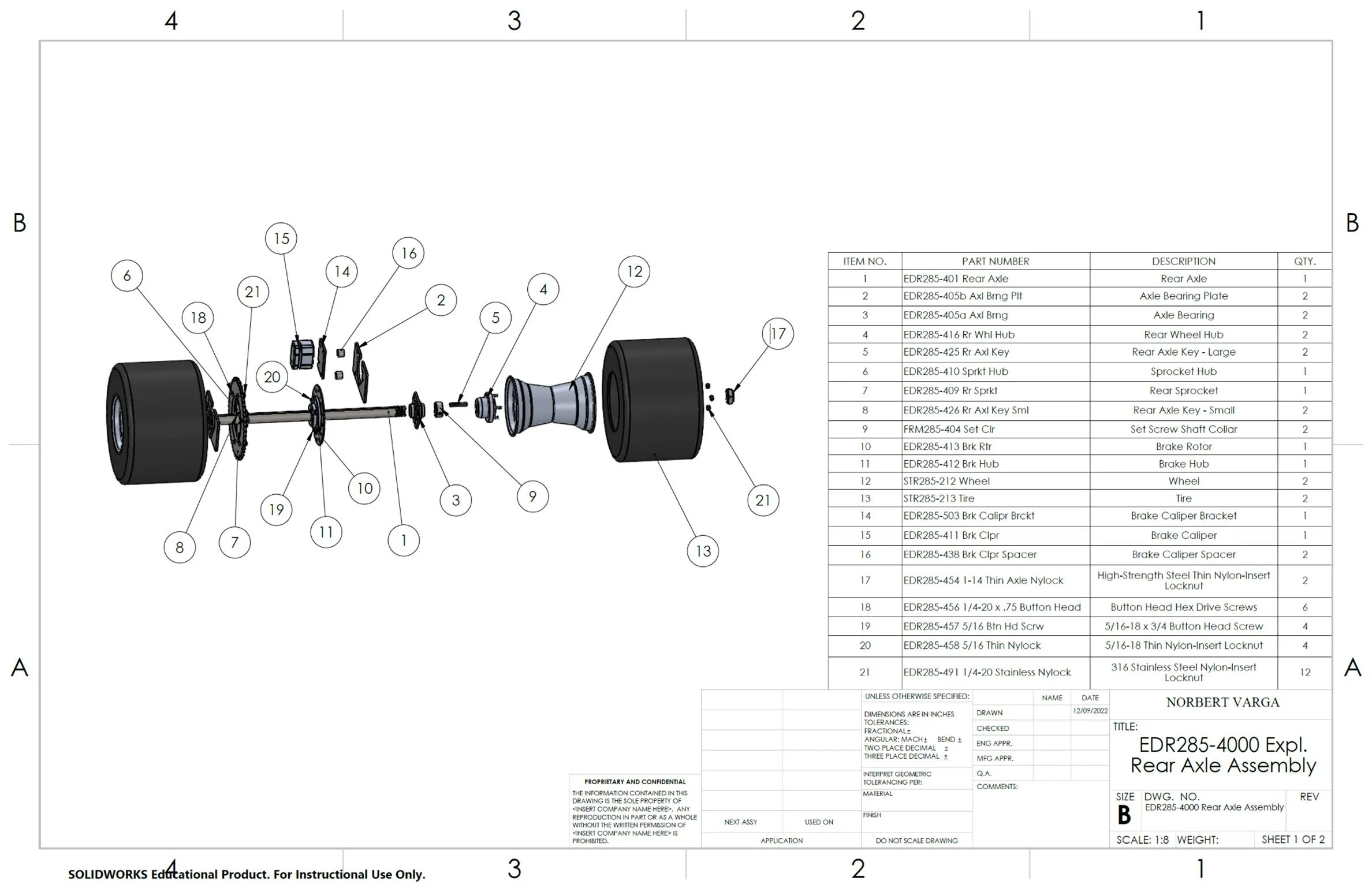
After all the commercial and manufacturing parts were modeled, multiple sub-assemblies were created to be used used for the final assembly of the Trike.
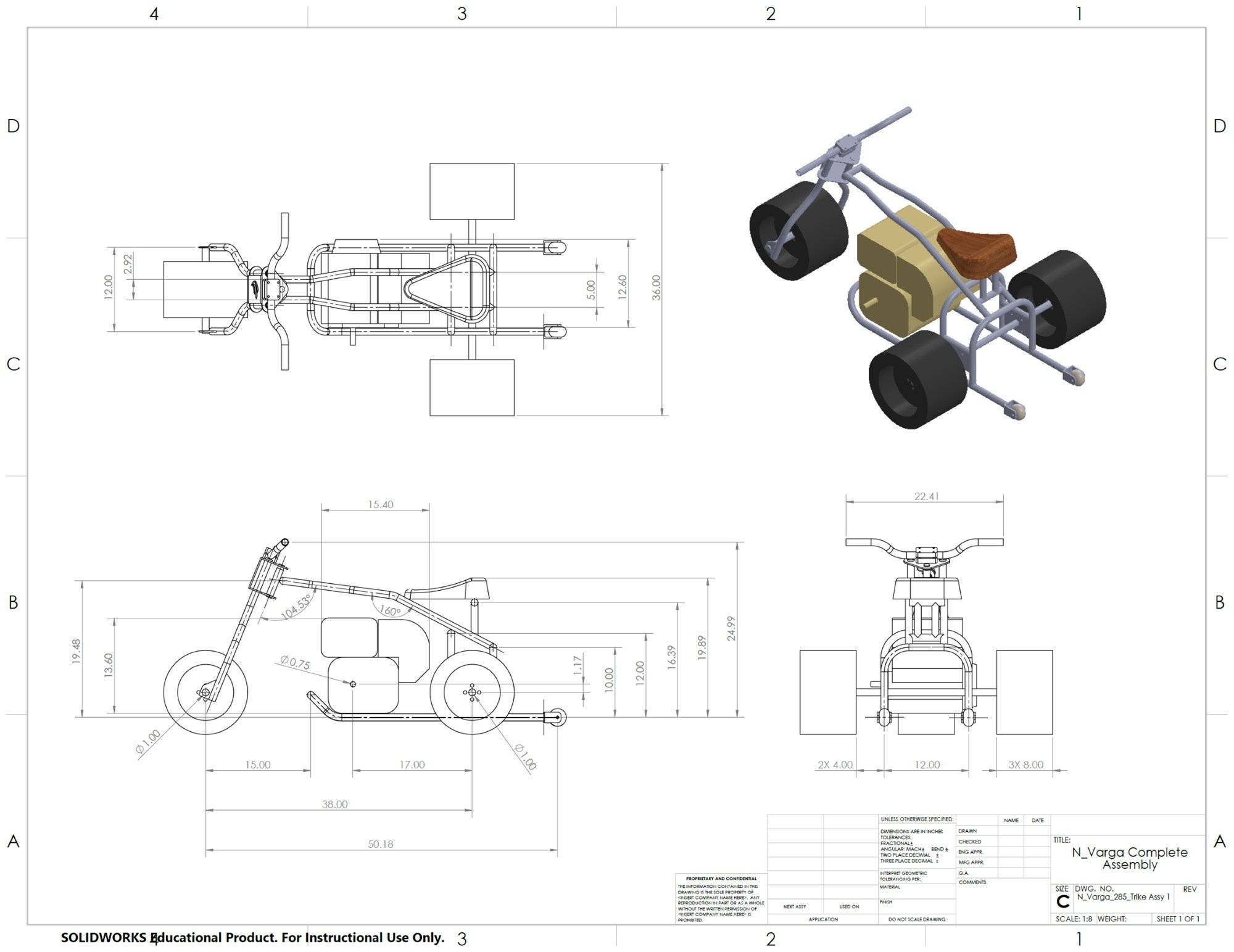
Complete Assembly Drawings
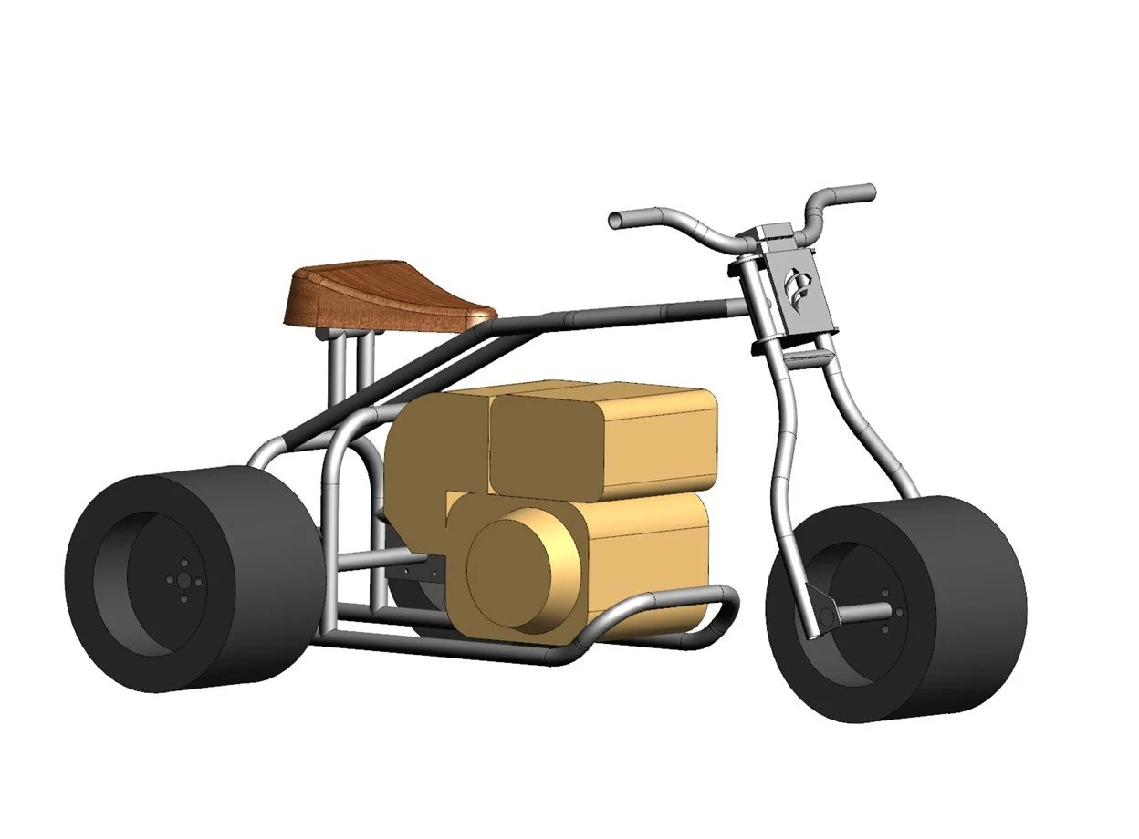
With all the fasteners, the final assembly consisted of over 260 parts, each with its own internal part number.
Stress Analysis
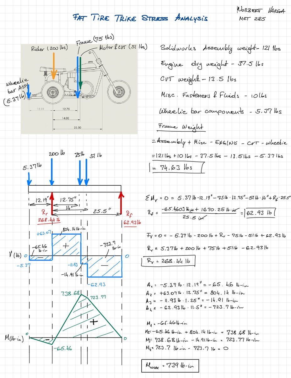
Stress analysis was preformed on the main frame members, the seat supports, and the brake pedal. The main frame members and the seat supports satisfied the design requirements from the start and no modifications were necessary. The original brake pedal design failed the stress analysis and needed to be re-designed. As part of this project the gear ratios were calculated as well to ensure that the trike does not exceed a 25-mph top speed.

Bill of Materials
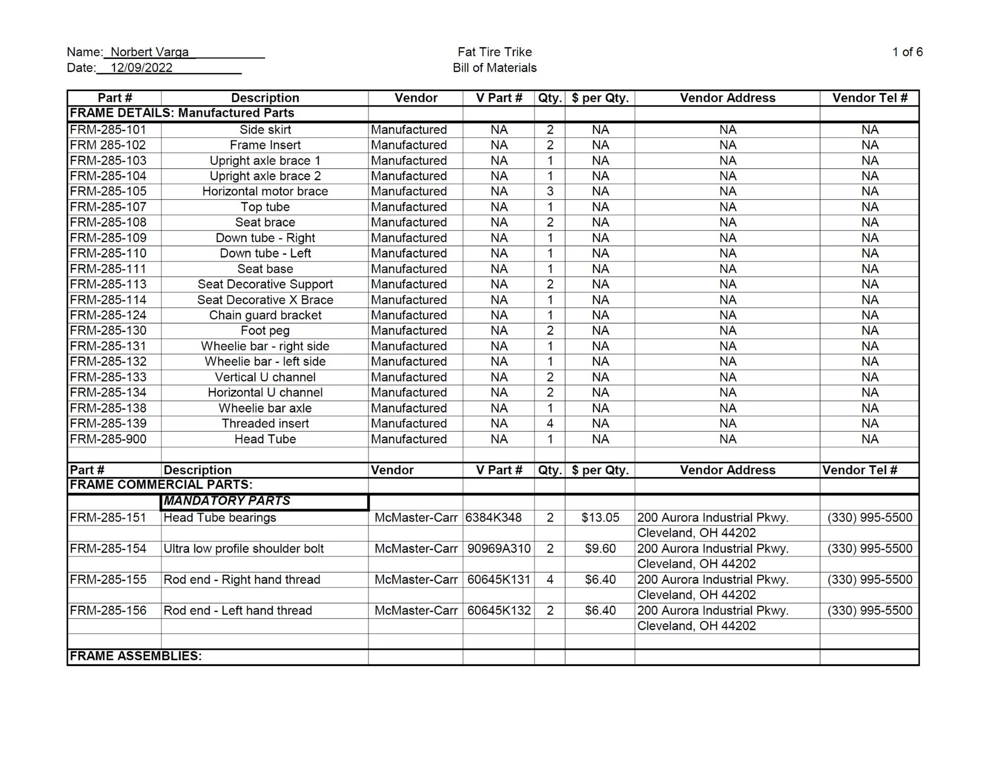
The bill of materials referenced every part of the build down to each nut and bolt. Parts were categorized and grouped. If the parts were going to be purchased, the vendor information, price, and their part numbers were referenced.
Detailed Drawings
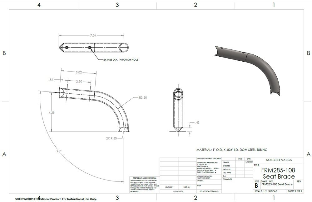
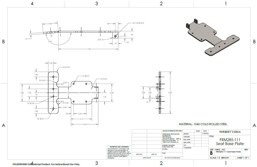
Every part that was going to be manufactured in-house needed a dimensioned shop drawing. This project had more than 40 shop drawings.
Purchase Orders & Raw Materials List
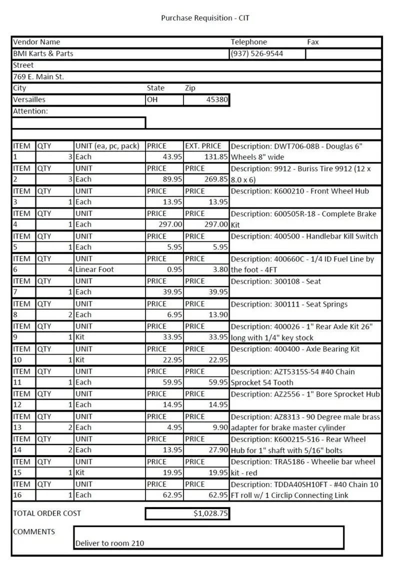
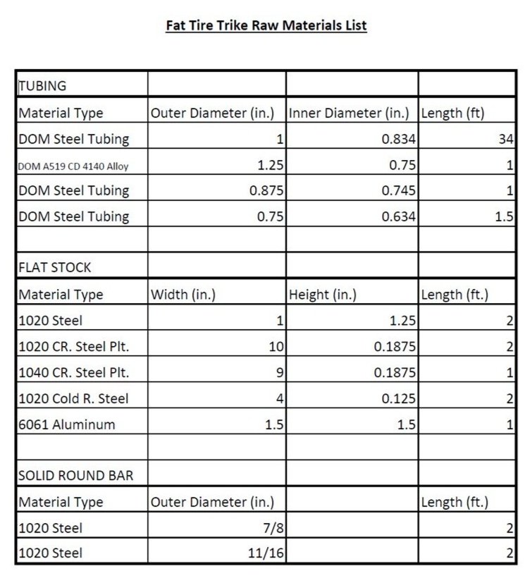
In order for all the commercial parts to be ordered between semesters, purchase orders and raw materials lists had to be created and submitted to the purchasing department. The purchase orders and raw materials lists consisted of nearly 80 line items.
Cost Analysis
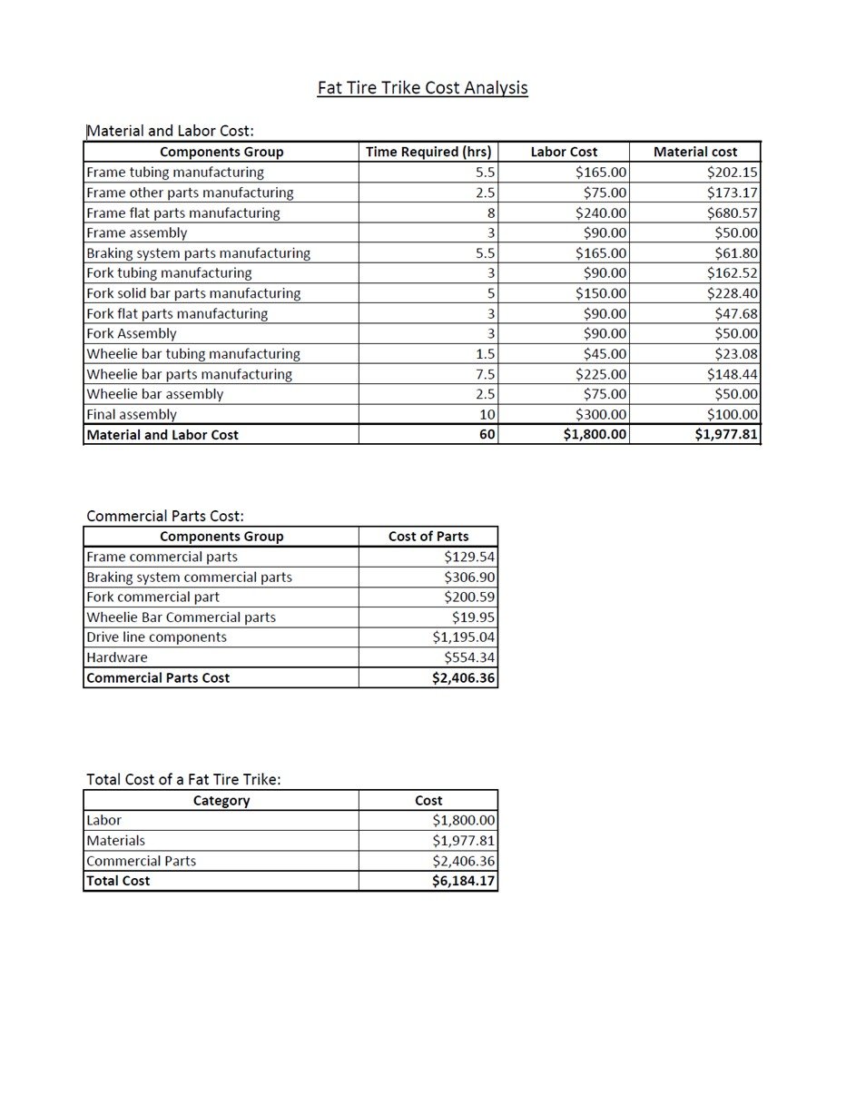
The cost of raw materials and commercial parts was added up and combined with the labor estimate to create the cost analysis for the project.
Manufacturing Process
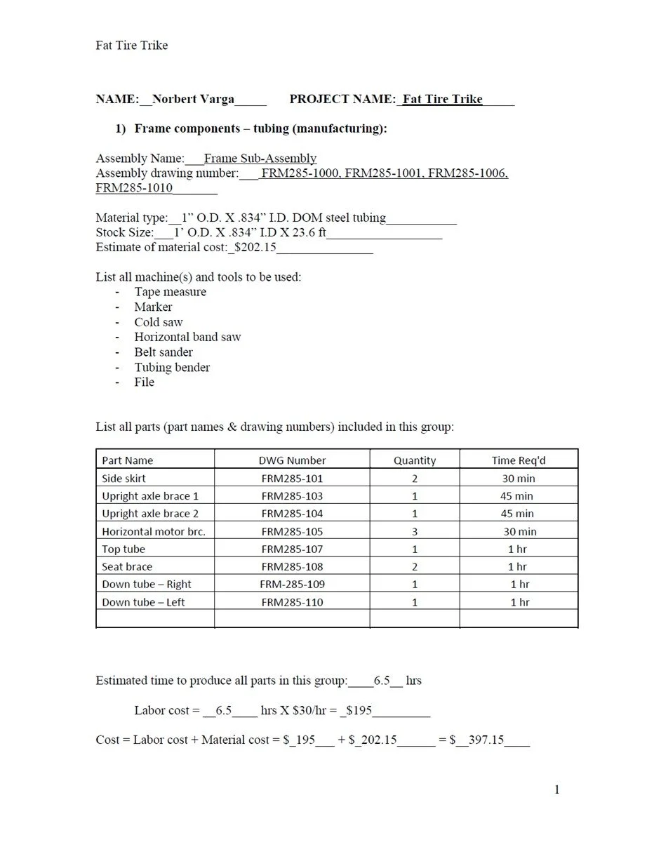
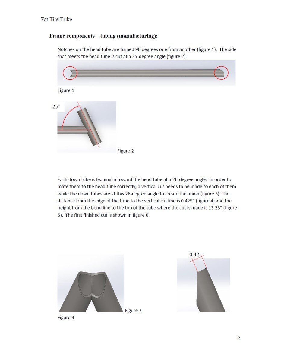
The manufacturing process accounts for all raw materials needed to manufacture the groupings of parts in each category. The tooling and the equipment to be used are also listed, as are the special instructions for the manufacturing process.