Capstone Manufacturing Project
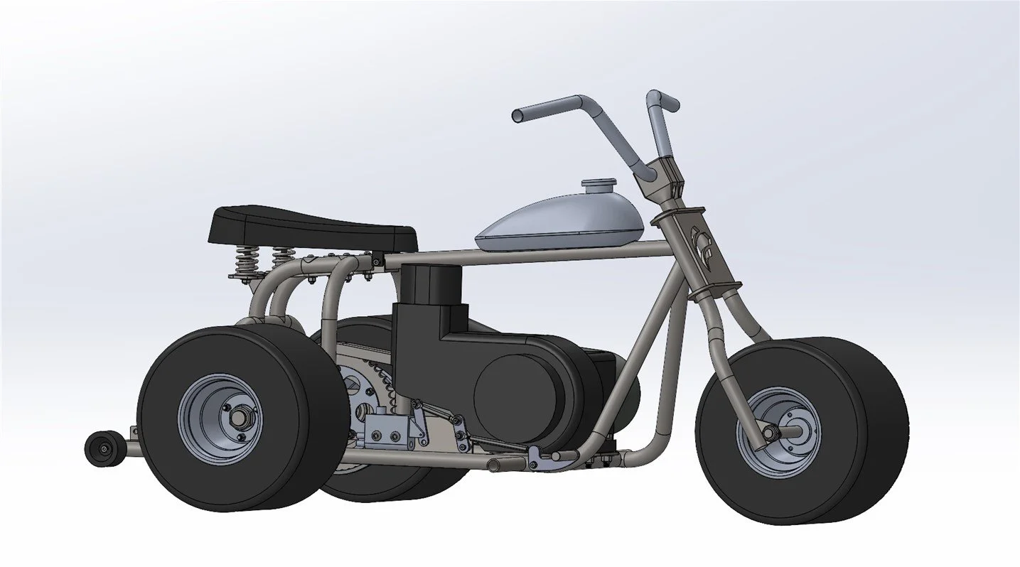
Bringing the Design to Life
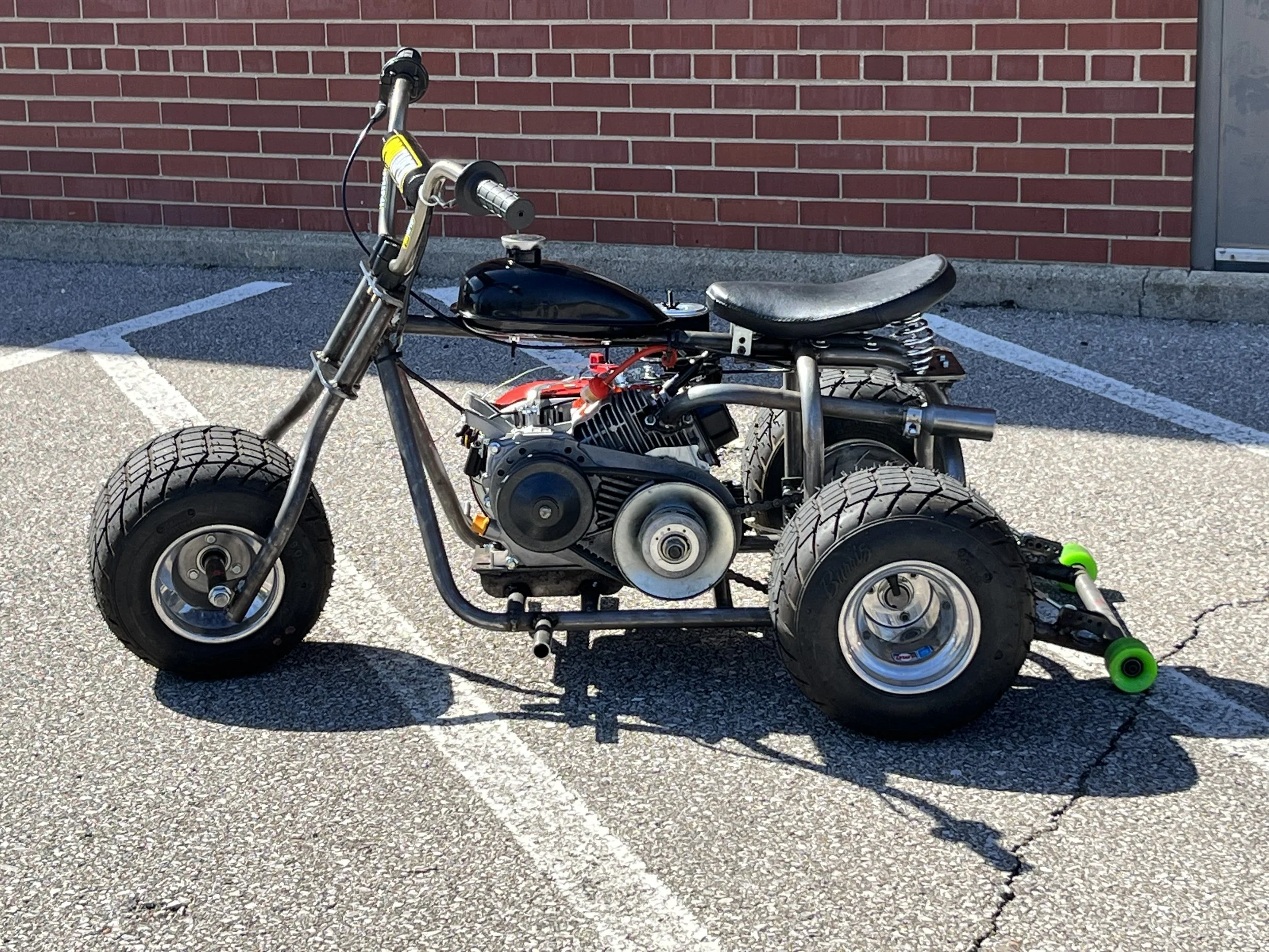
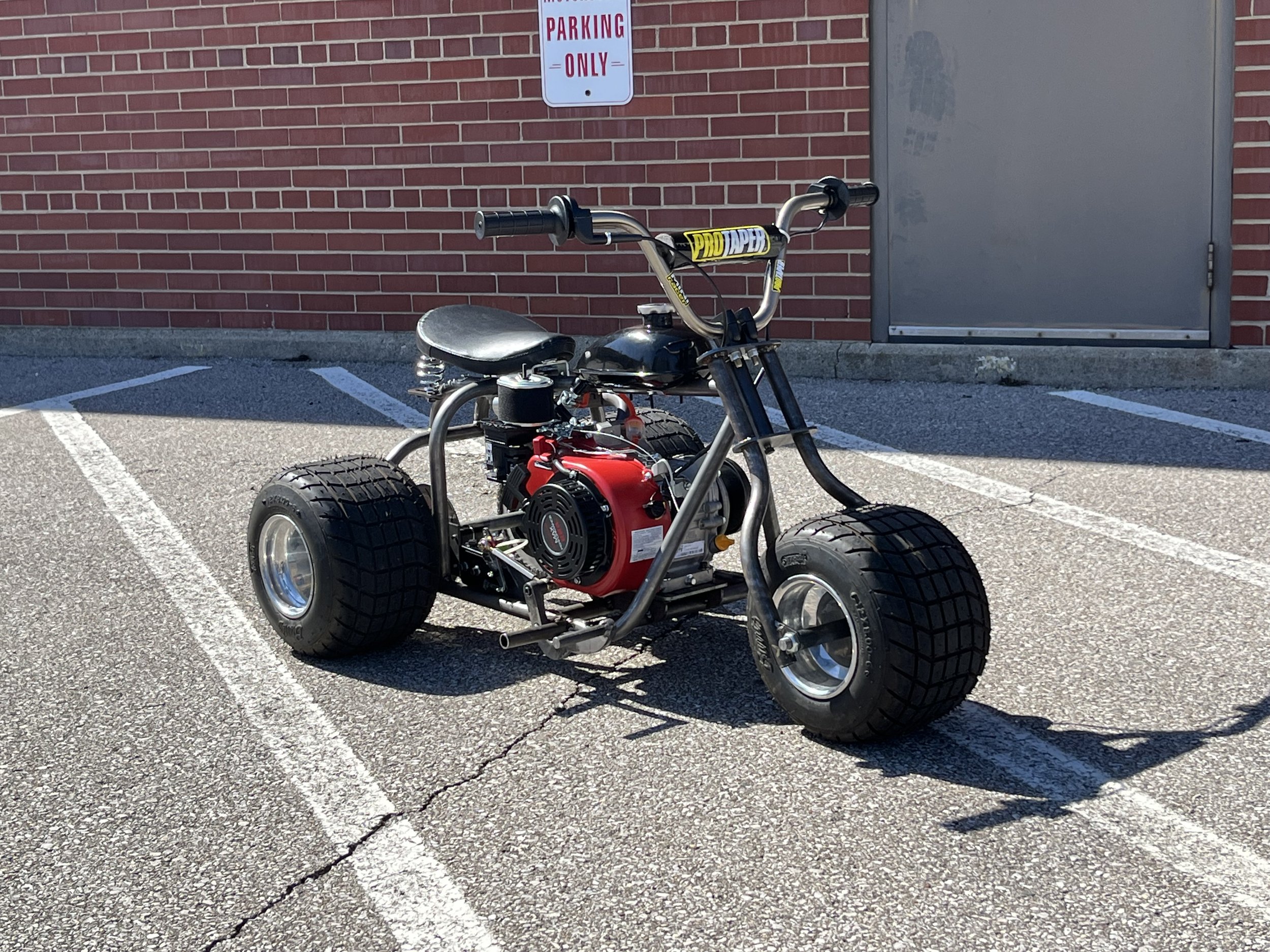
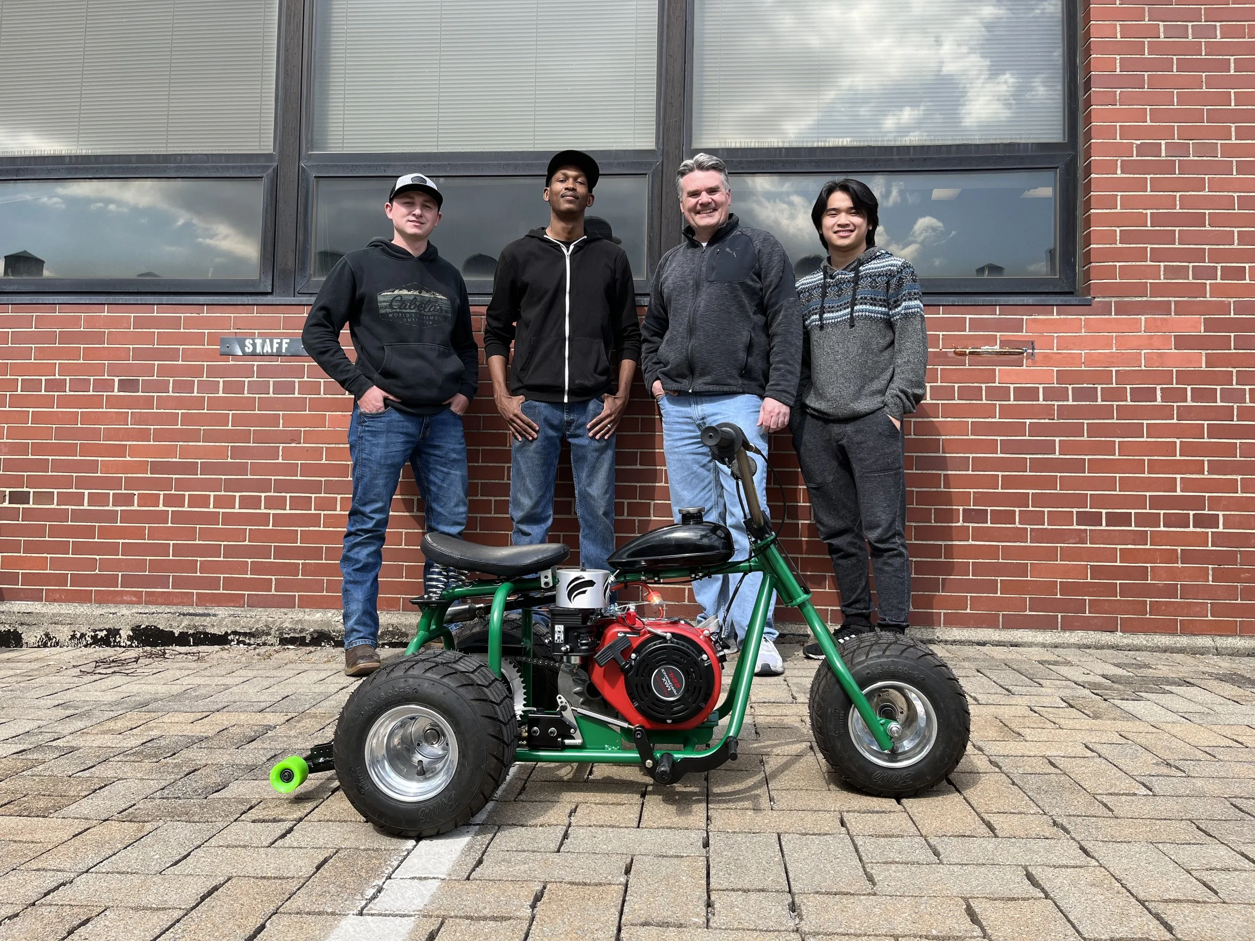
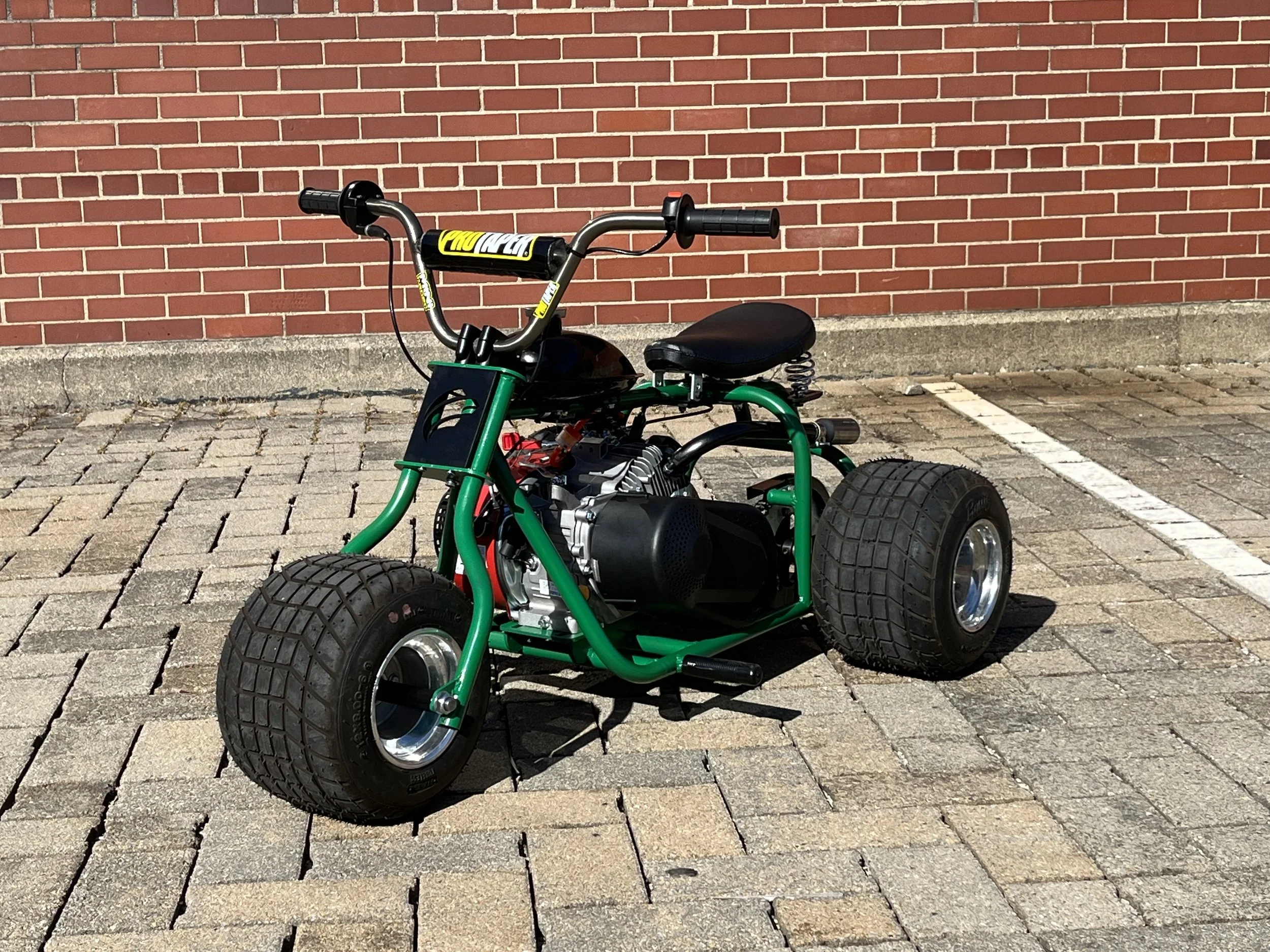
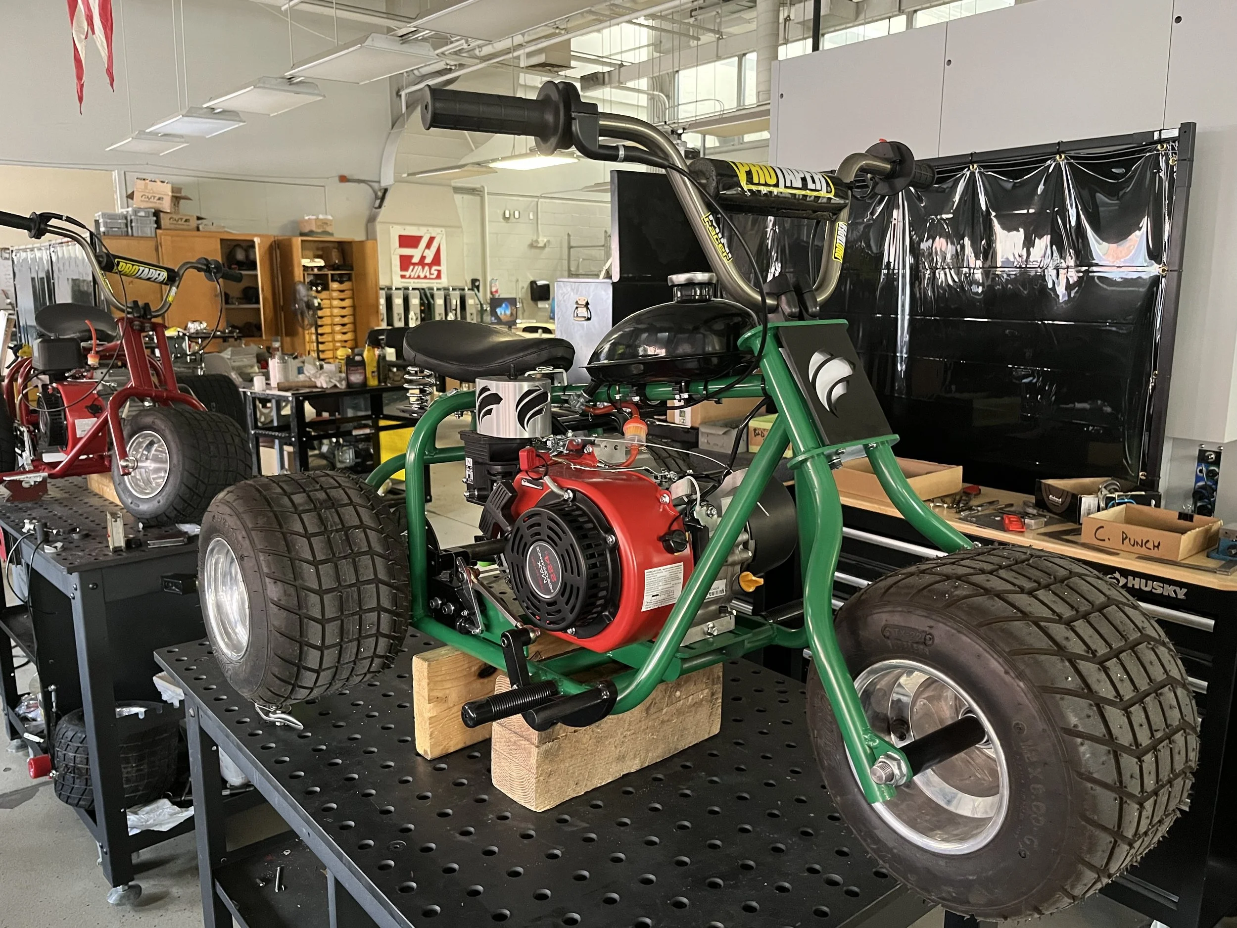
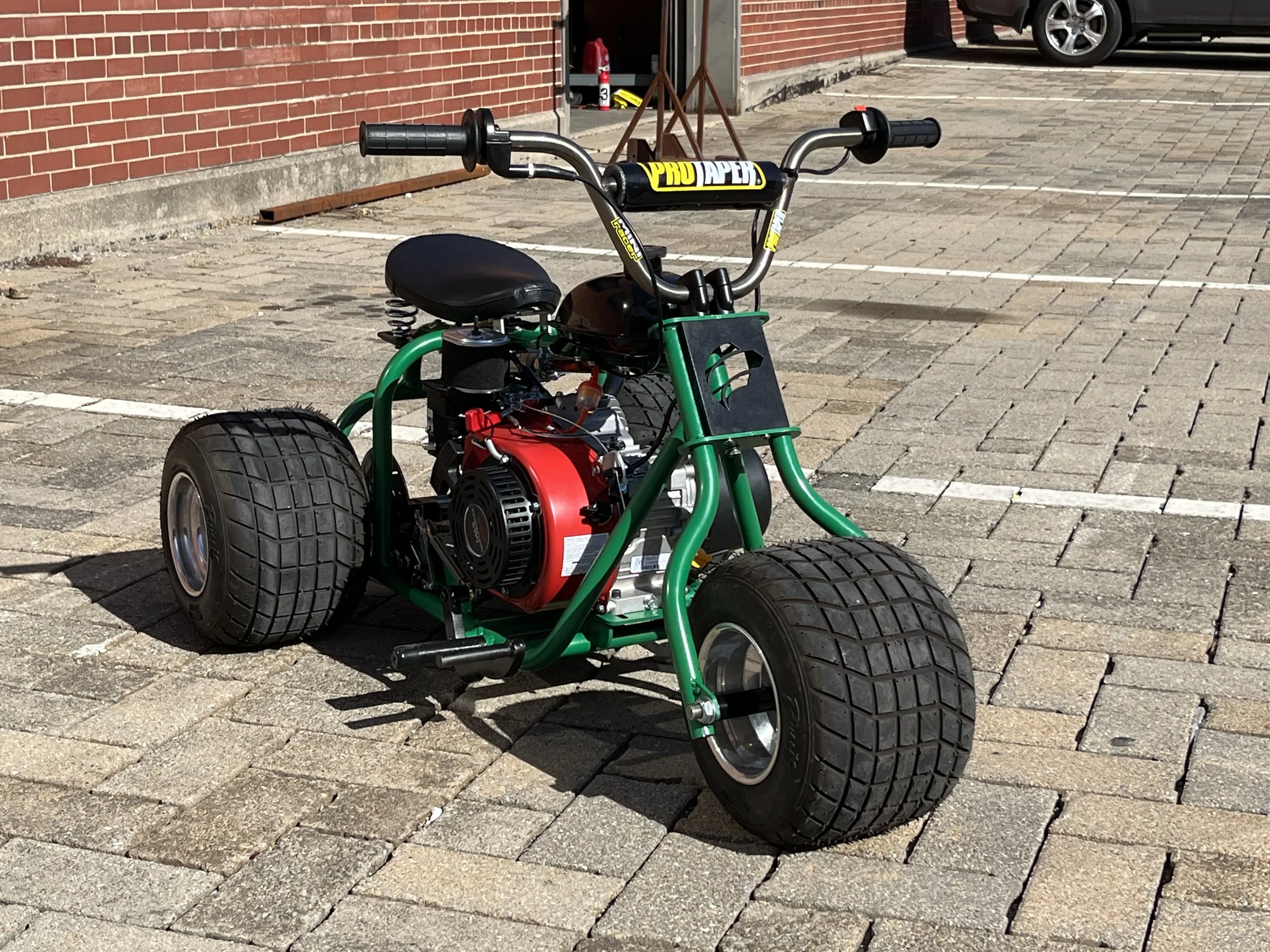
My design was one of three chosen by the faculty for manufacturing. As the teams were being assembled, I volunteered to be the team leader for the manufacturing phase of the project. My responsibilities included creating weekly work schedules for the build, teaching team members how to use machines and equipment when needed, creating special jigs to aid in the manufacturing process, and contributing to the build process. My contributions to the build will be documented on this page.
Week Two of the Build
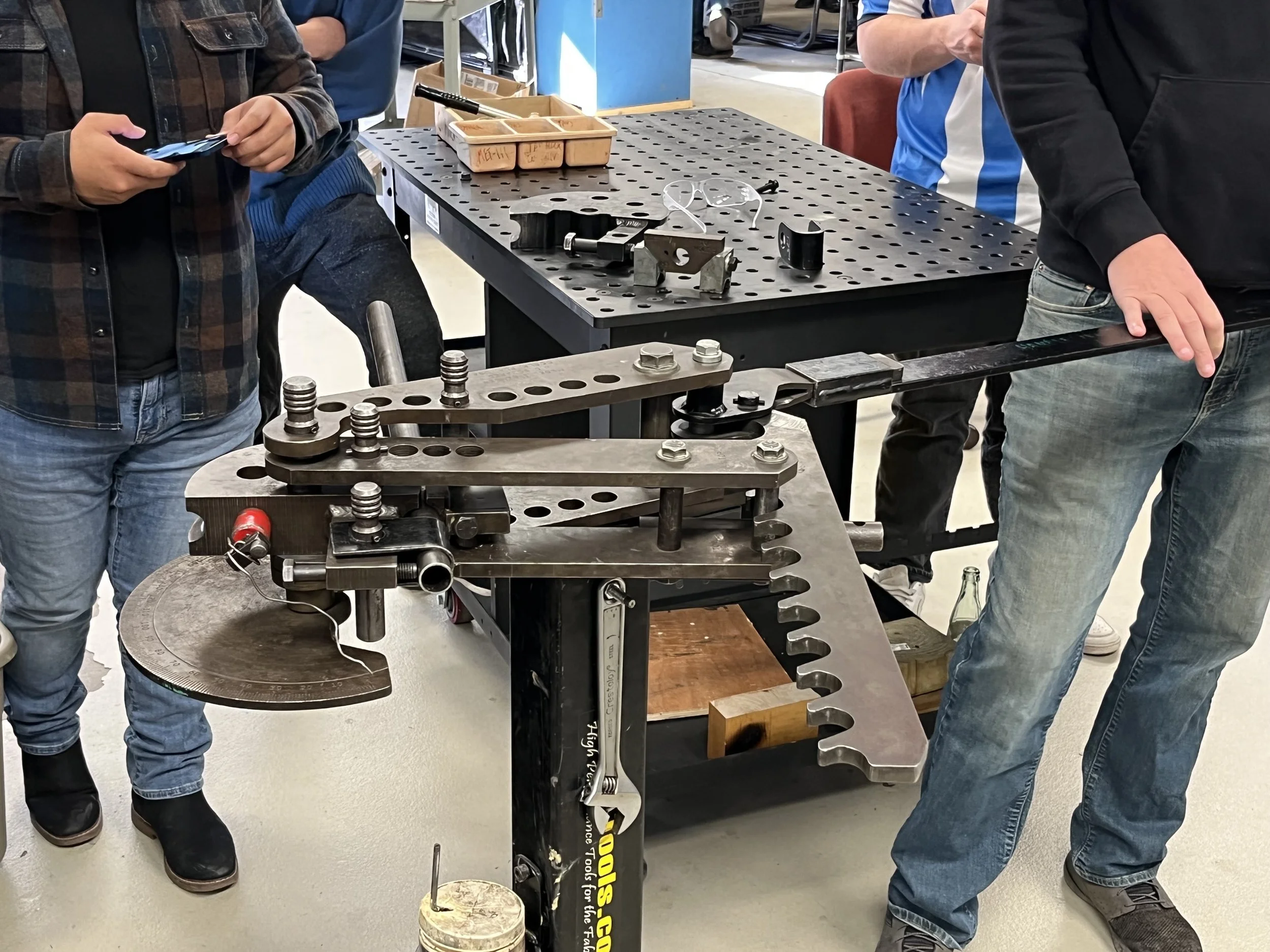
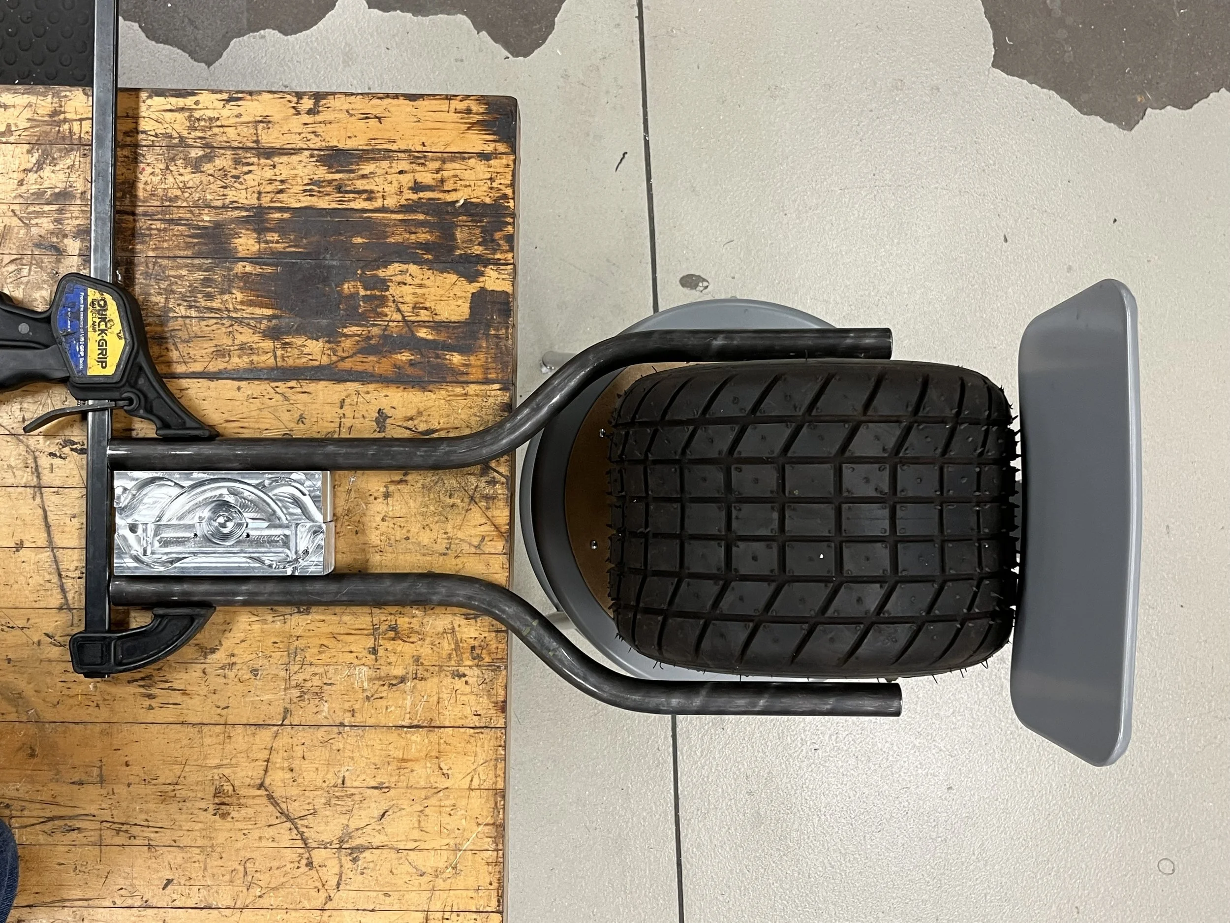
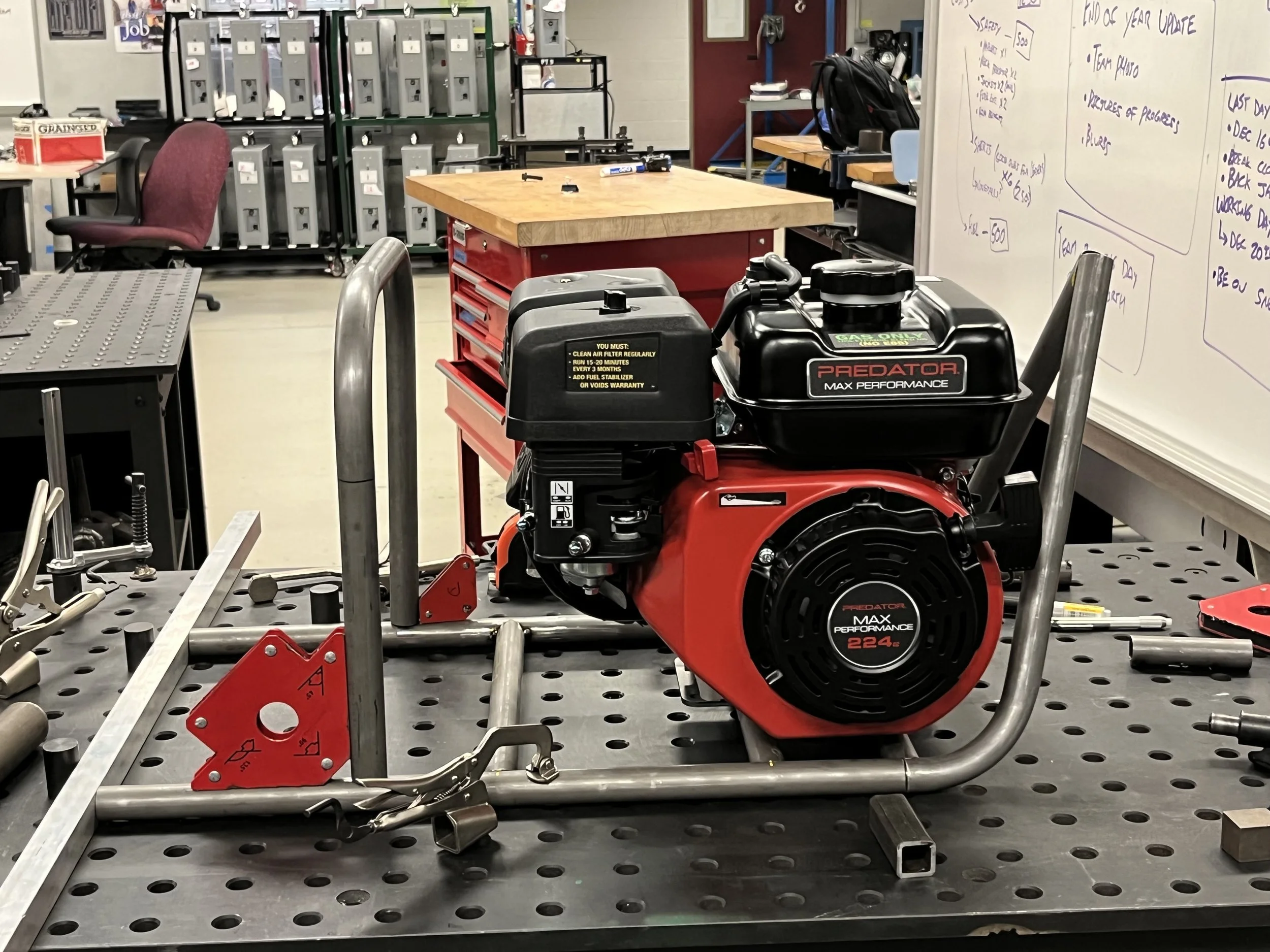
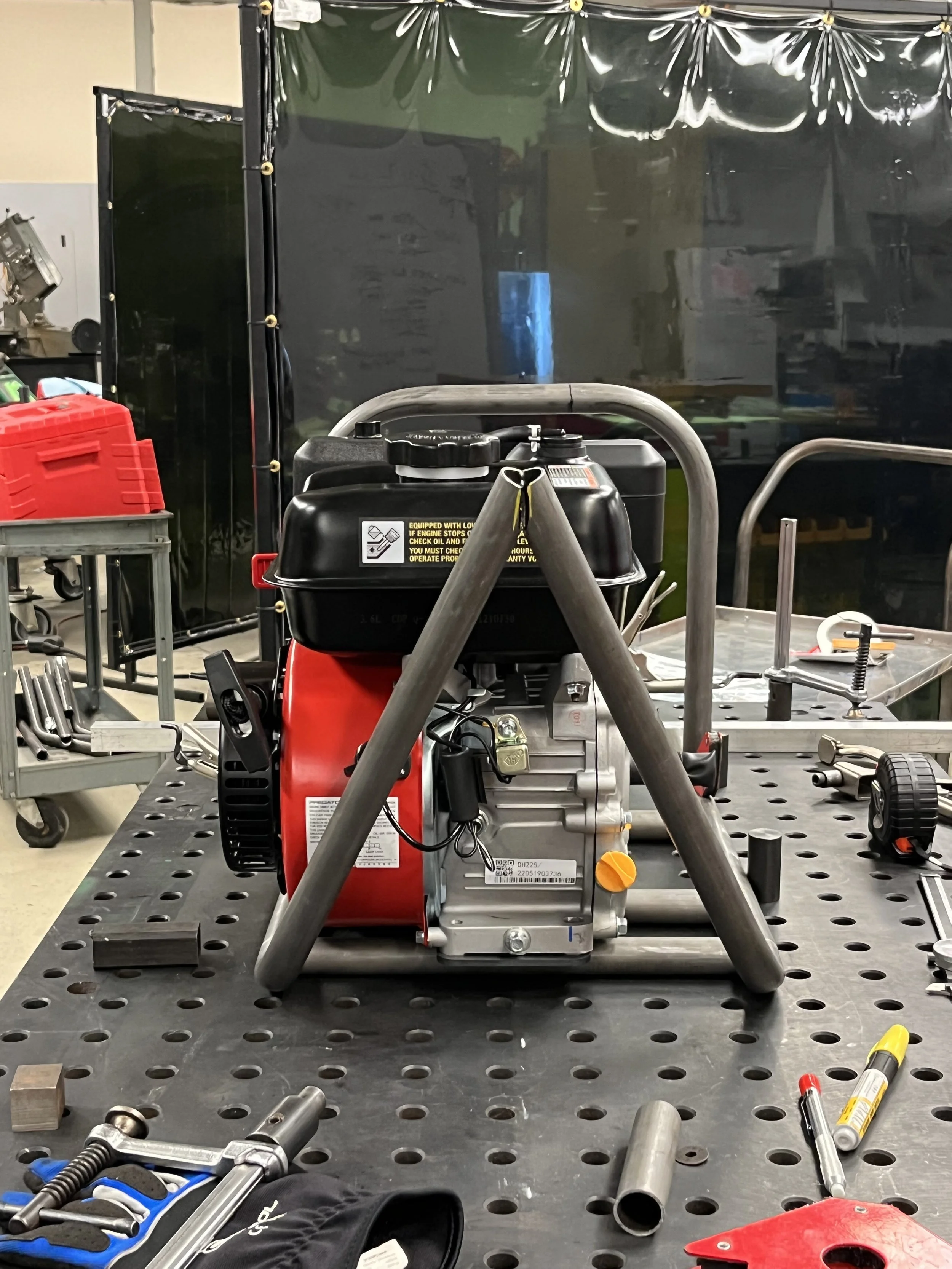
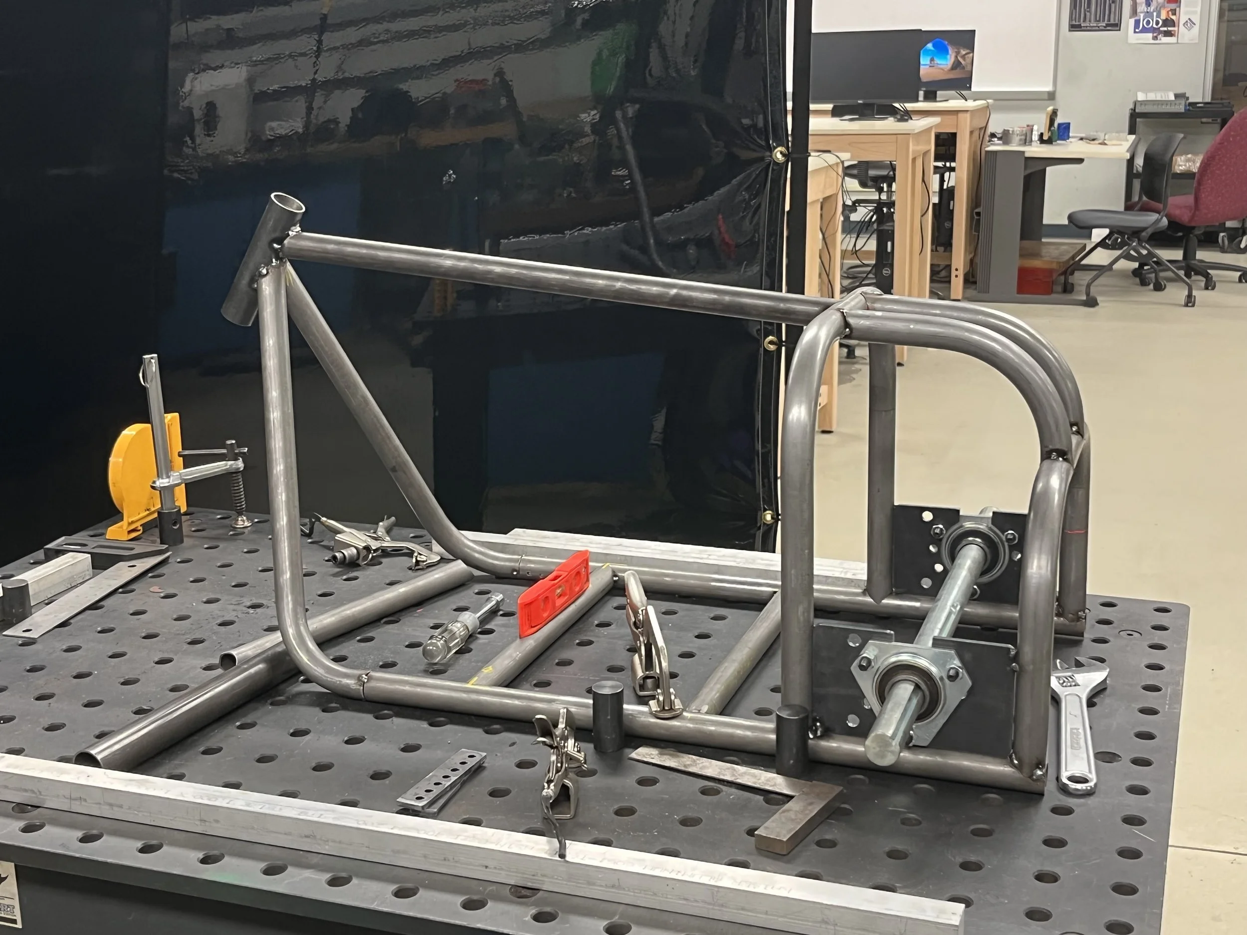
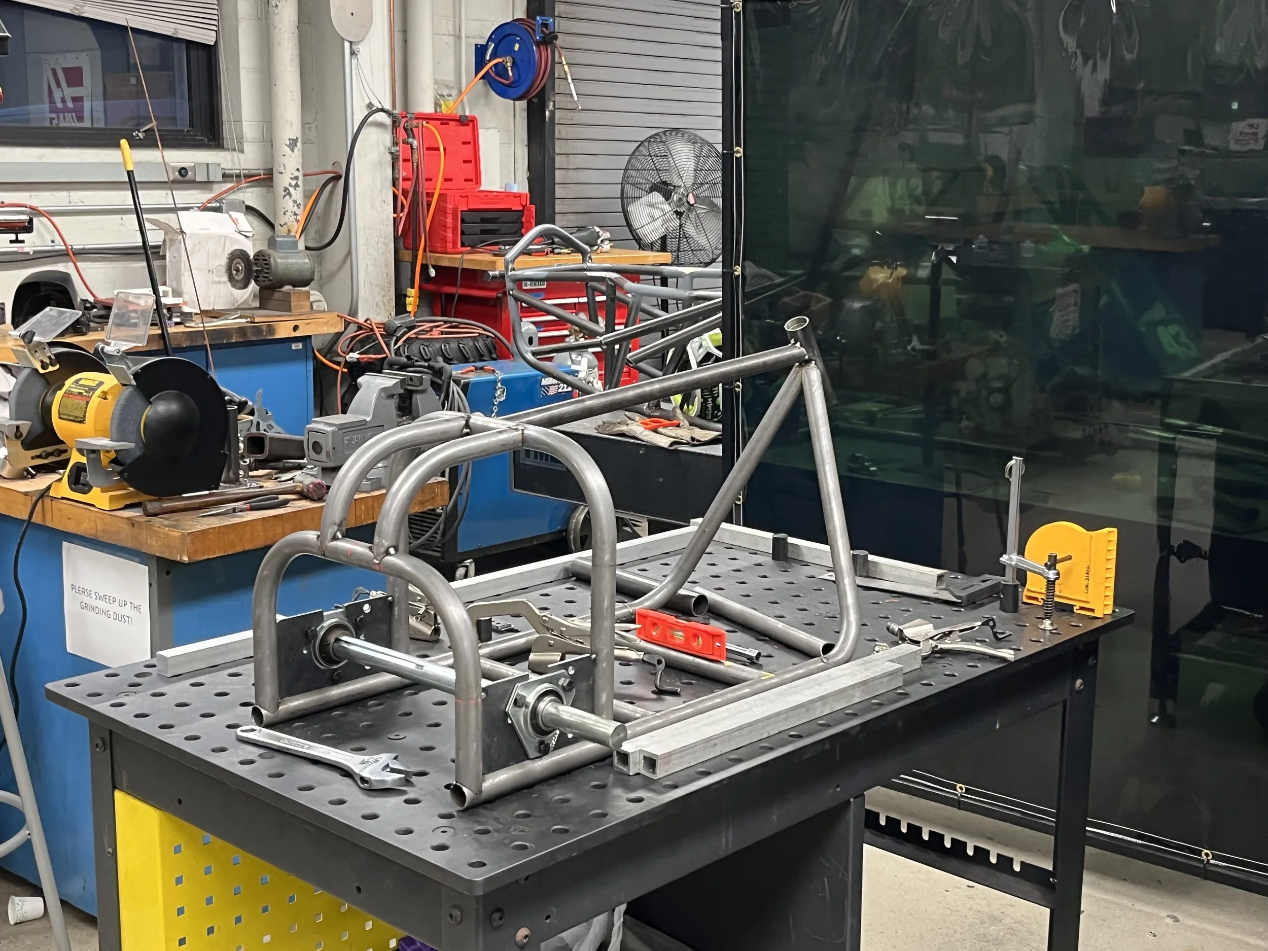
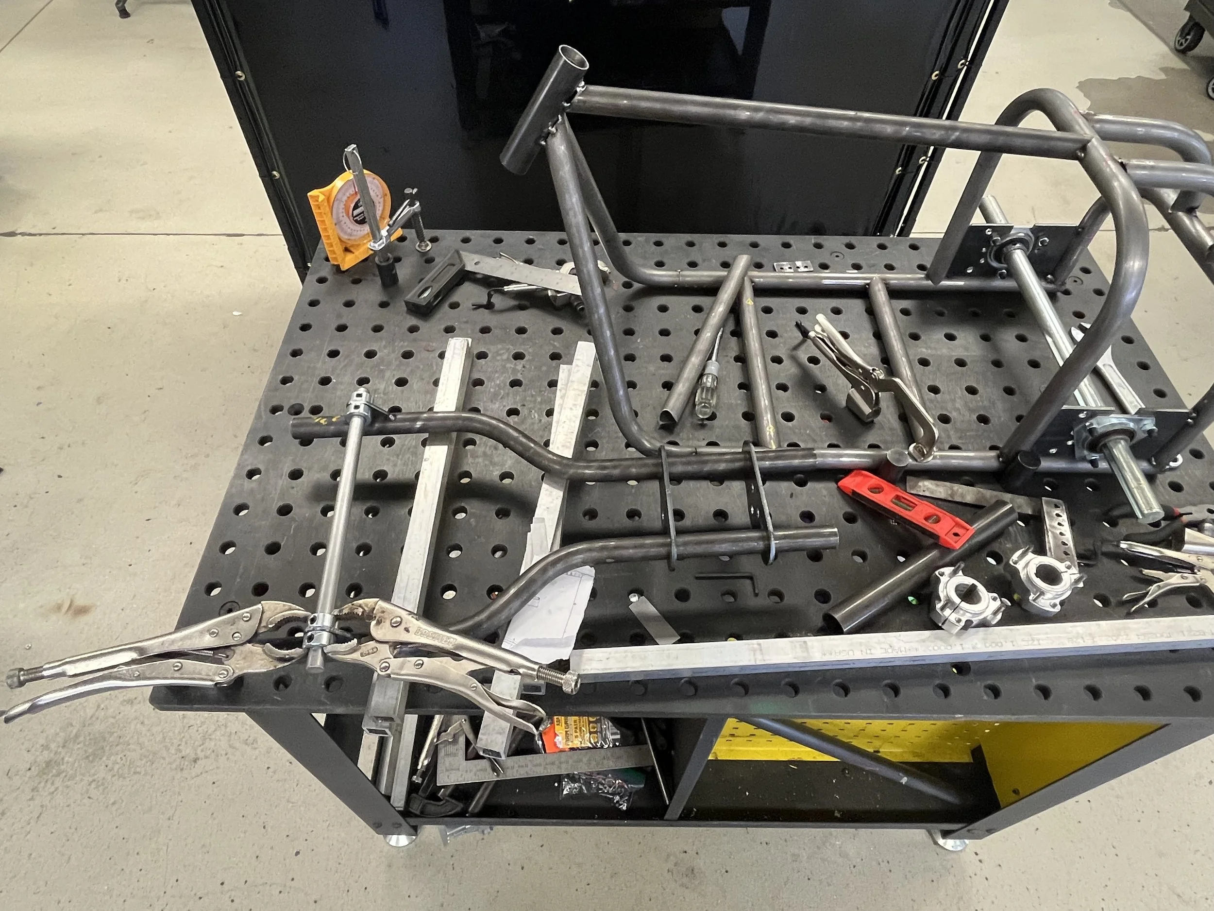
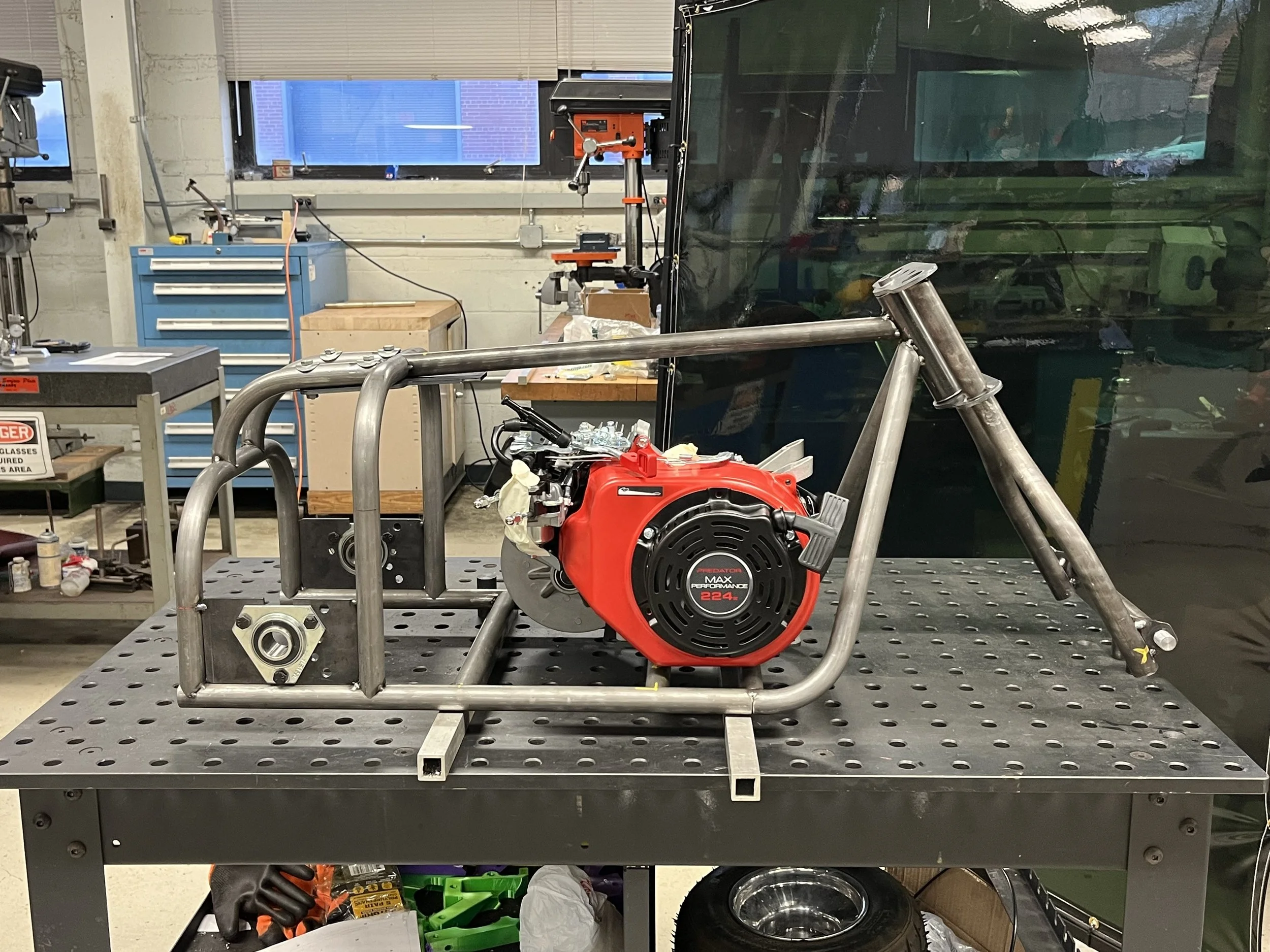
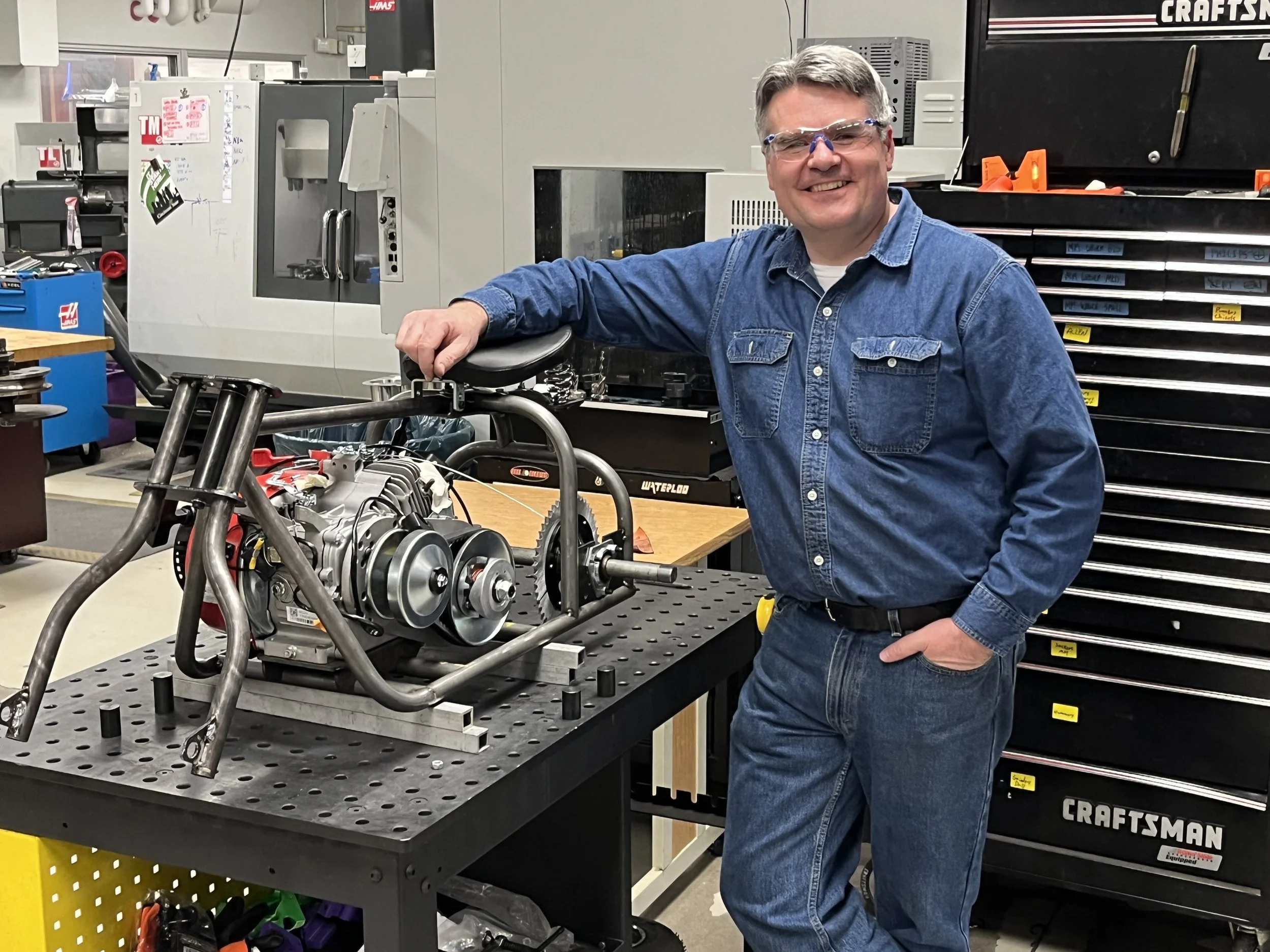
The frame was starting to take shape. Most of my time was spent on bending tubing with a team member, aligning parts, and welding. In addition to my projects, I was also helping a team member on the lathe. Before we left for the day, I grabbed one of the engines that was delivered that day and placed it inside the frame for reference.
Week One of the Build
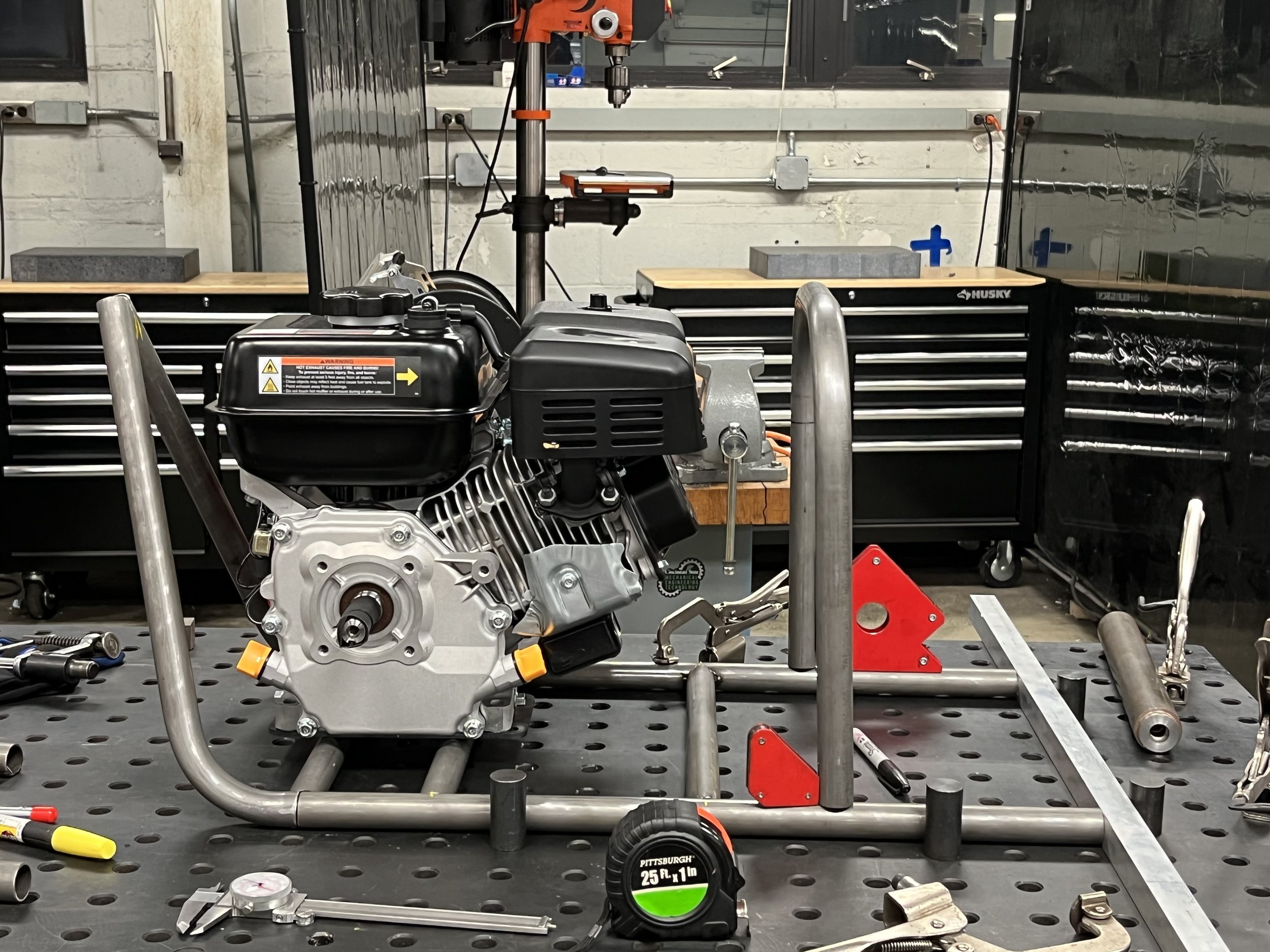
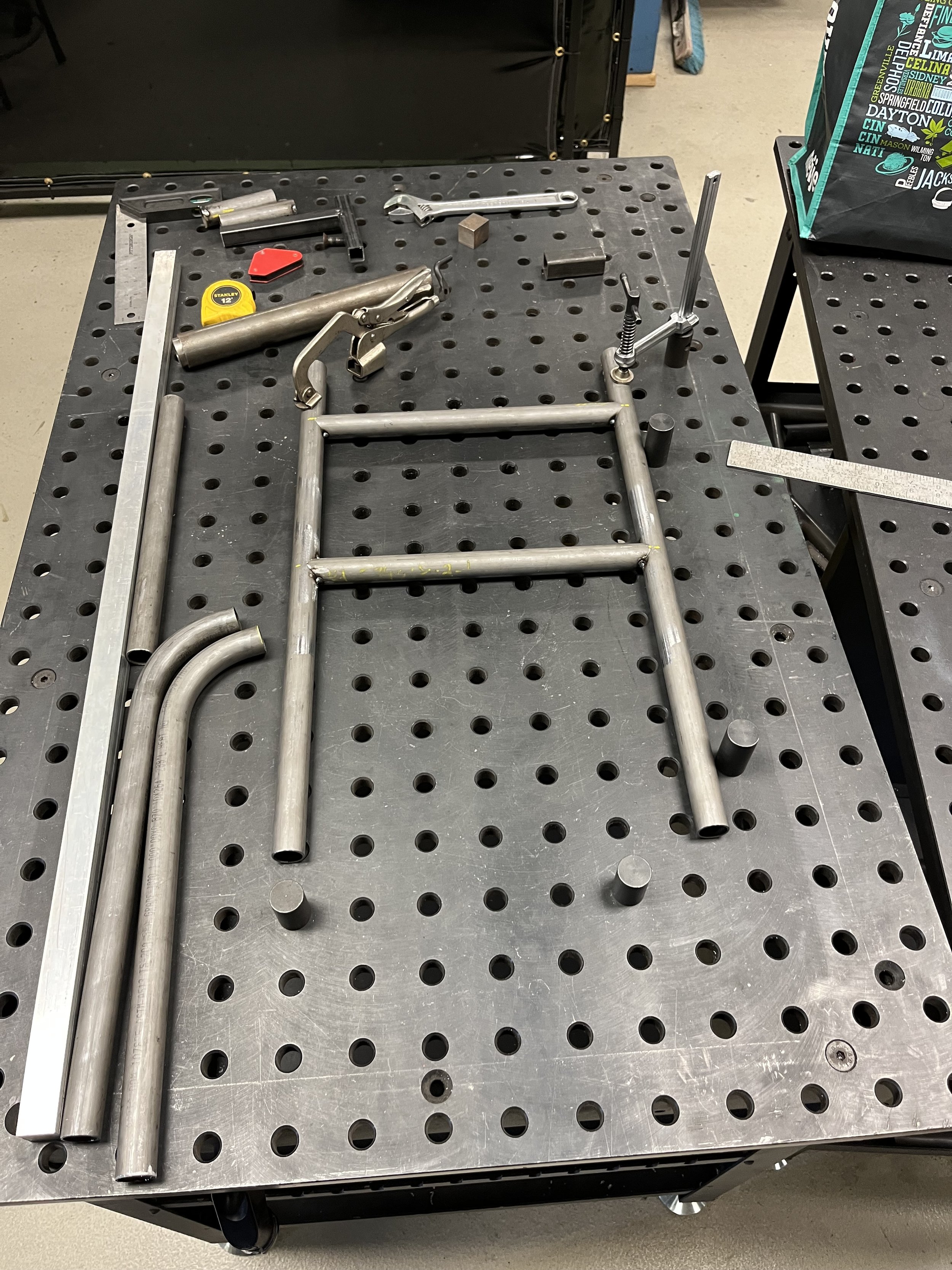
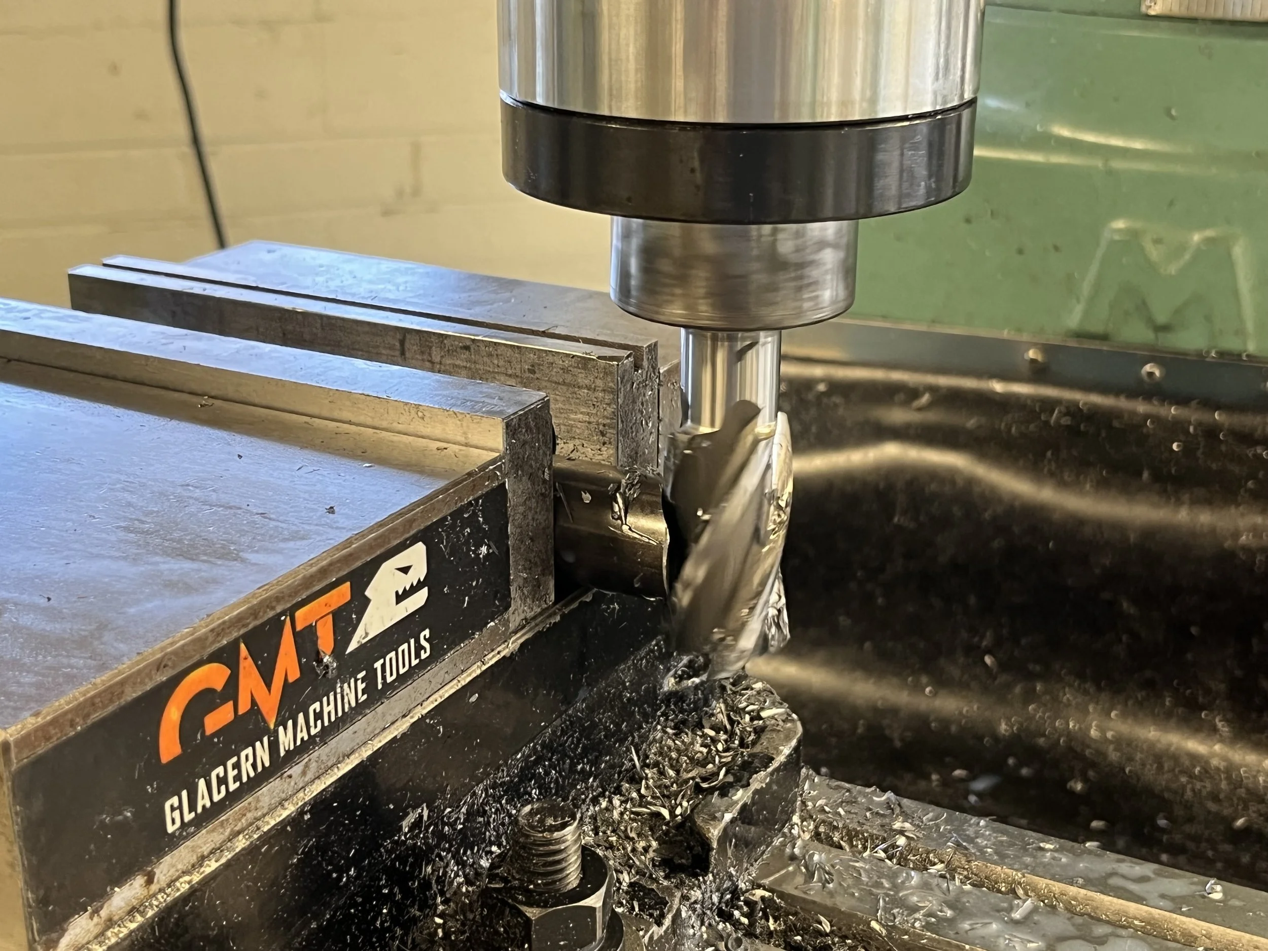
In the first week of the build, my primary focus was on making sure that we have a square and level base to work from. For this reason, I helped one of the team members setup the mill to notch the cross-member tubing so that we have a tight fit. The plan worked, and after tacking the base together, we were ready to start adding to it.
As the team lead, I was summoned to the purchasing department to collect all the parts that were ordered based on my purchase orders. These parts needed to be inventoried, and this was done by all team members whenever we waited on a machine or equipment to be freed up. During the first week of the build, I was teaching one of the team members how to use the lathe, and I also helped with bending the tubing for the other parts of the frame.
Week Three of the Build
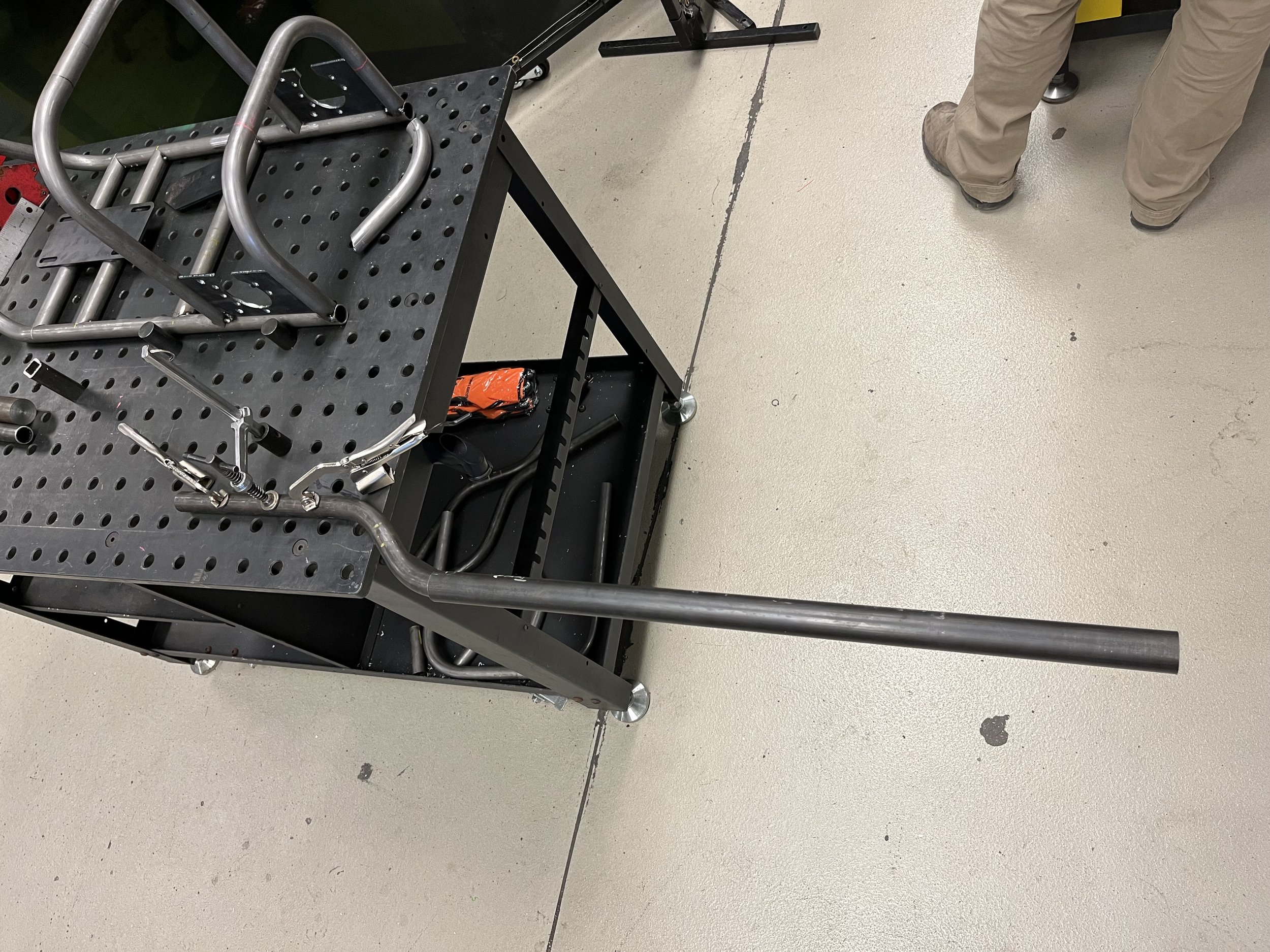
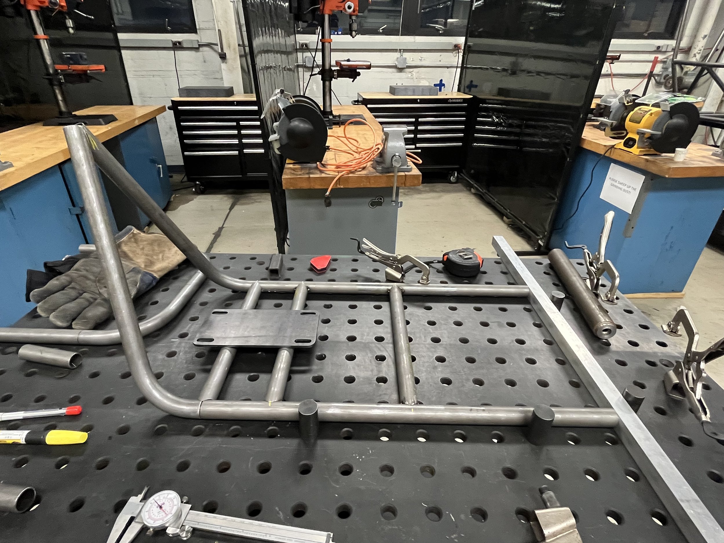
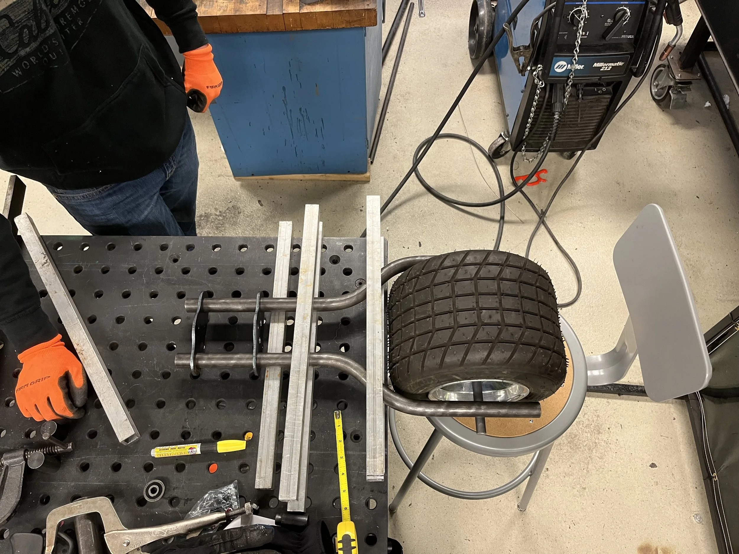
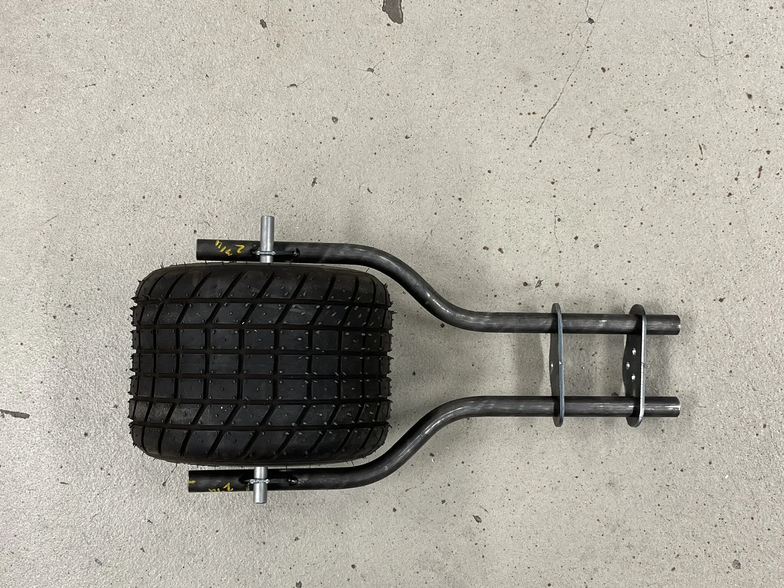
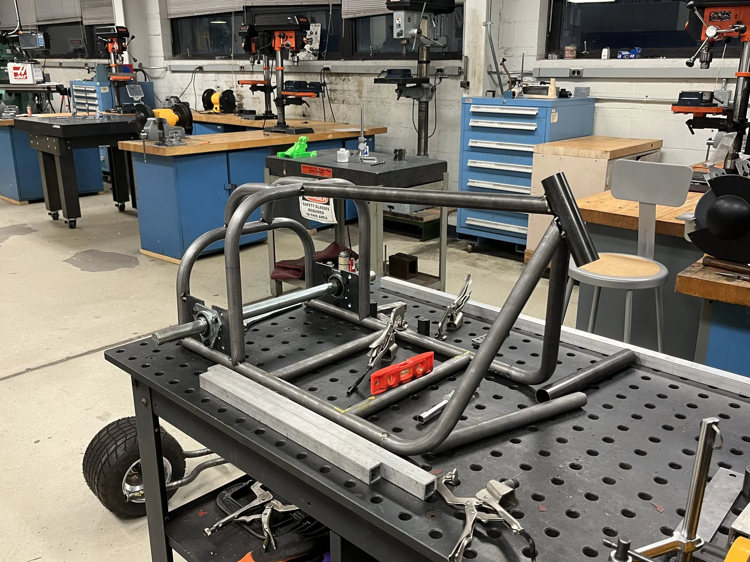
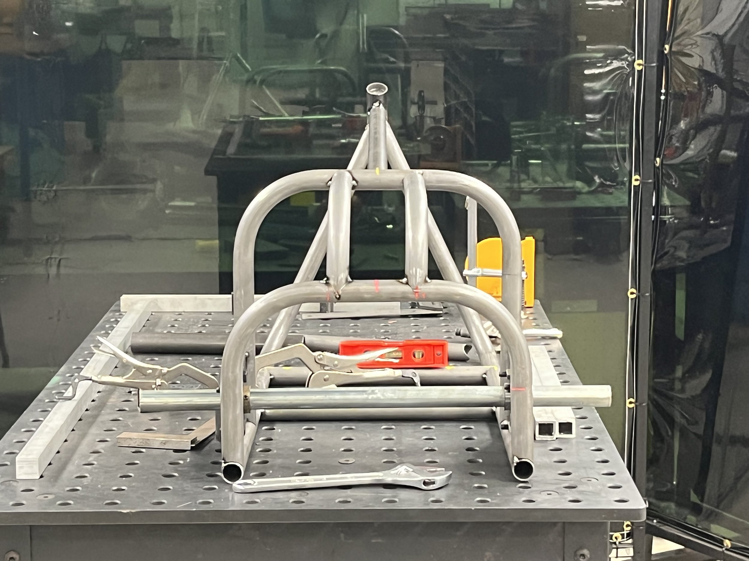
This week I spent most of my time bending the tubing for the forks. The first attempt was a failure, and it took some creative problem solving to get to the result seen in the photos. I had to make some design changes due to the limitations of the tubing bender, which then caused me to have to re-design a few other parts associated with the forks. I tacked together the rear of the frame with help from a team member, and then we squared the rear axle to make sure the trike was going to roll straight.
Week Four of the Build
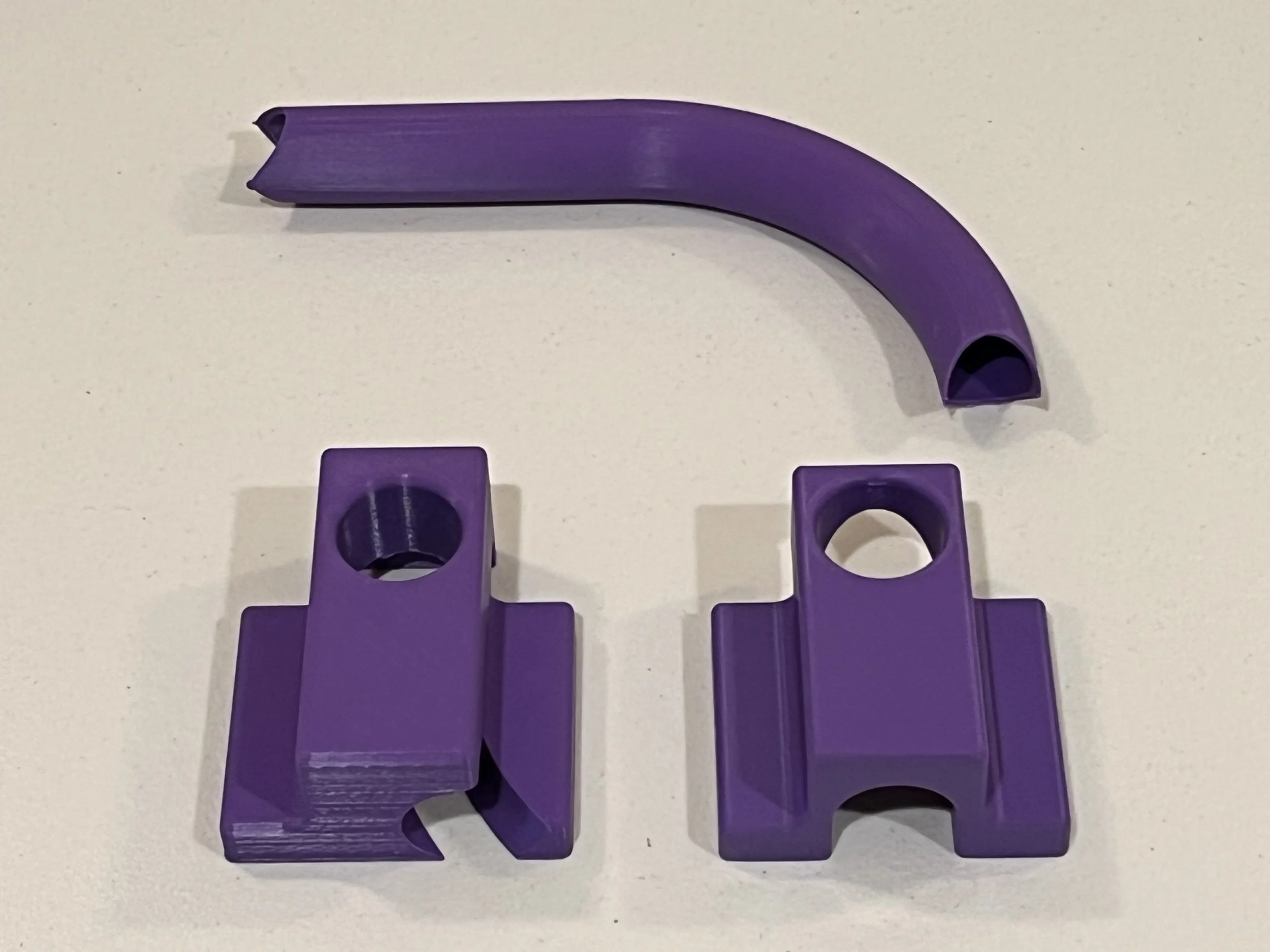
This was a big week for the team as we finished assembling the frame of the trike. The team member who was responsible for bending the seat base tubing ran into an issue last week where he couldn’t notch one of the pieces due to the curvature in the part. To help him overcome this issue, I 3D printed a template of the piece as well as jigs that he could use to make the necessary cuts.
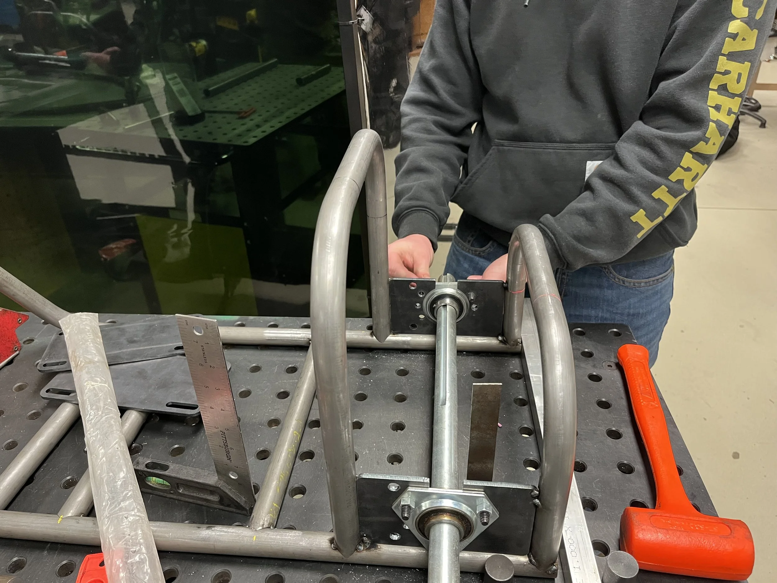
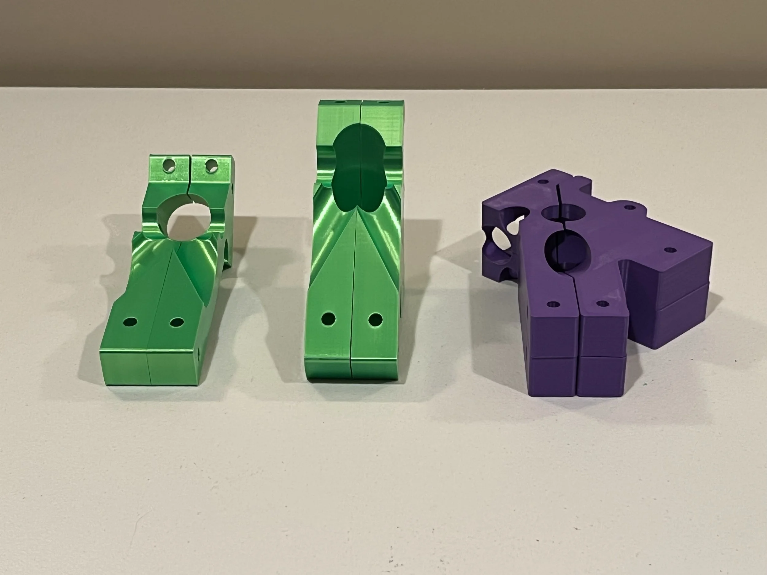
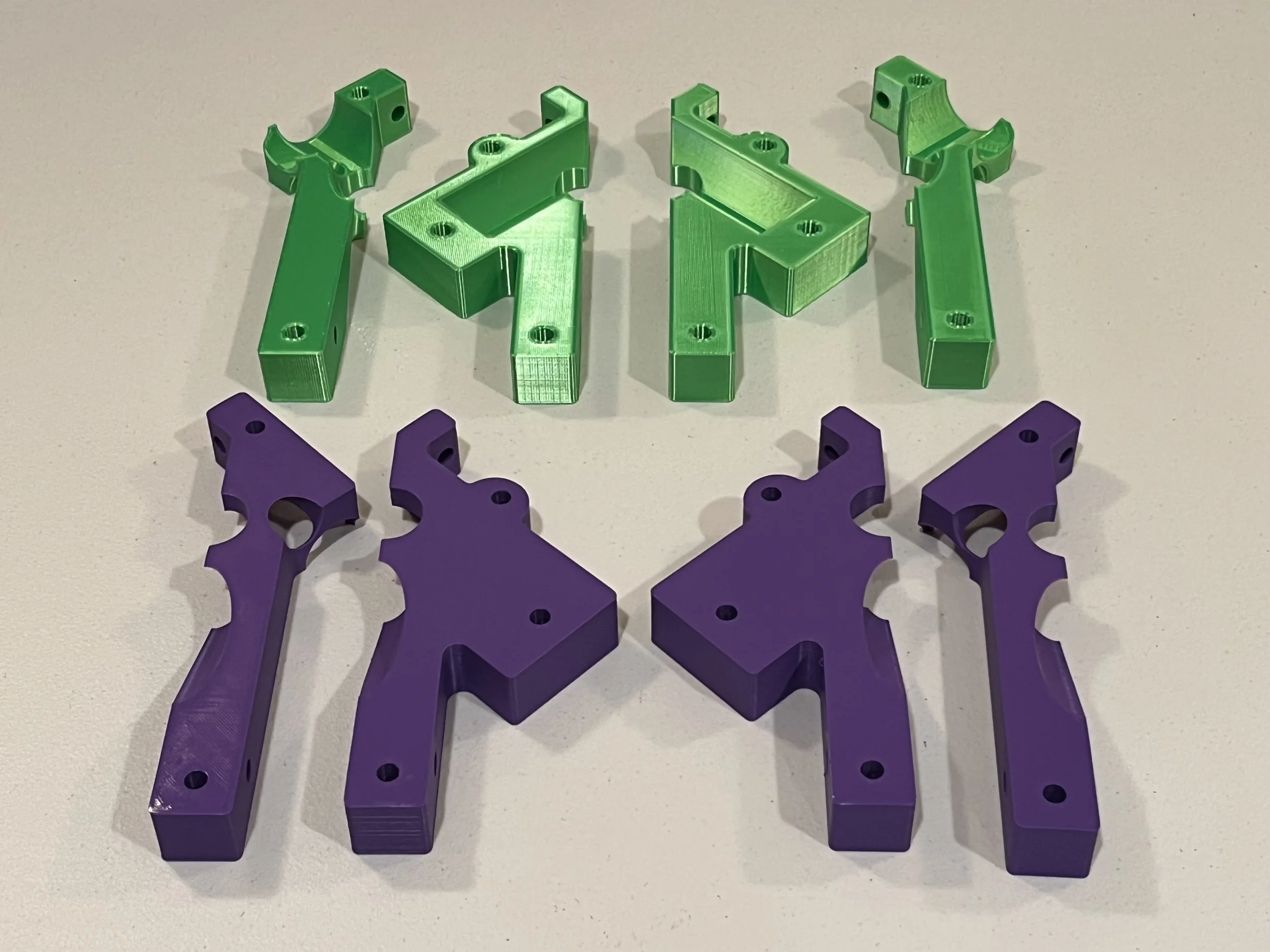
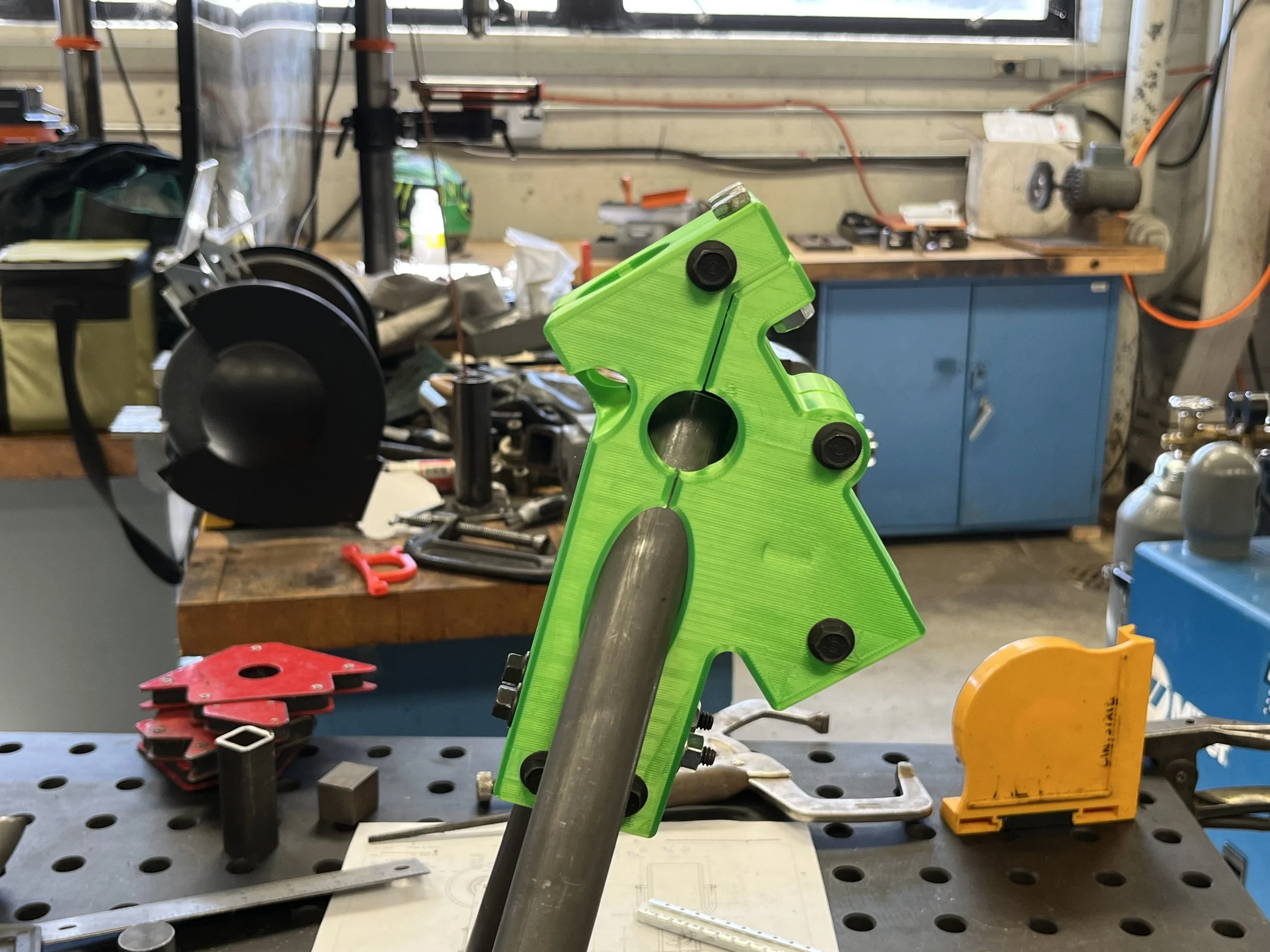
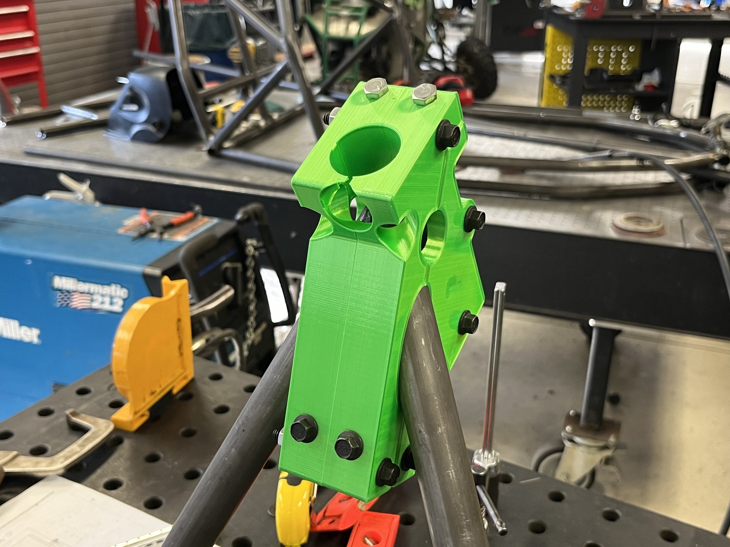
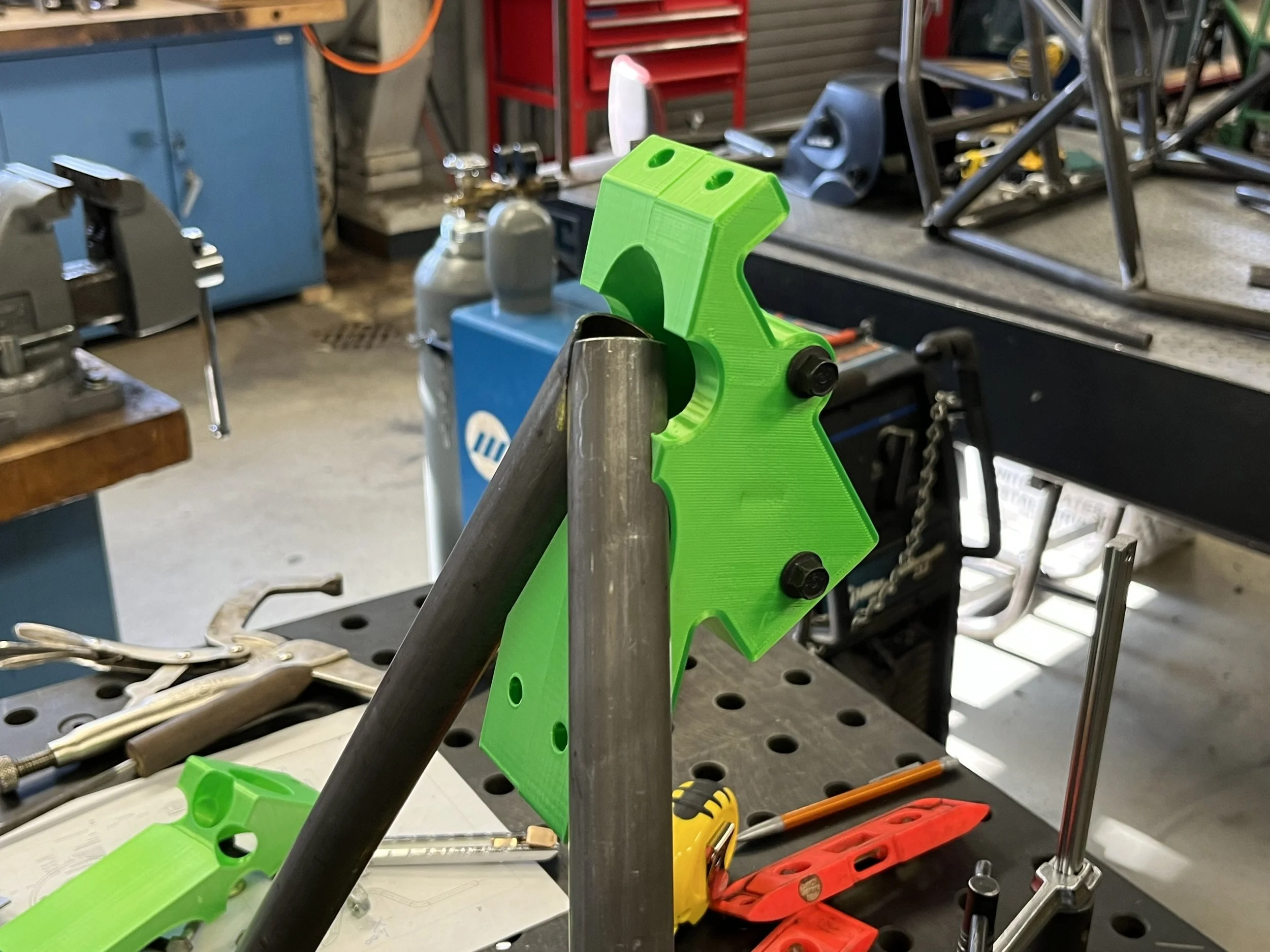
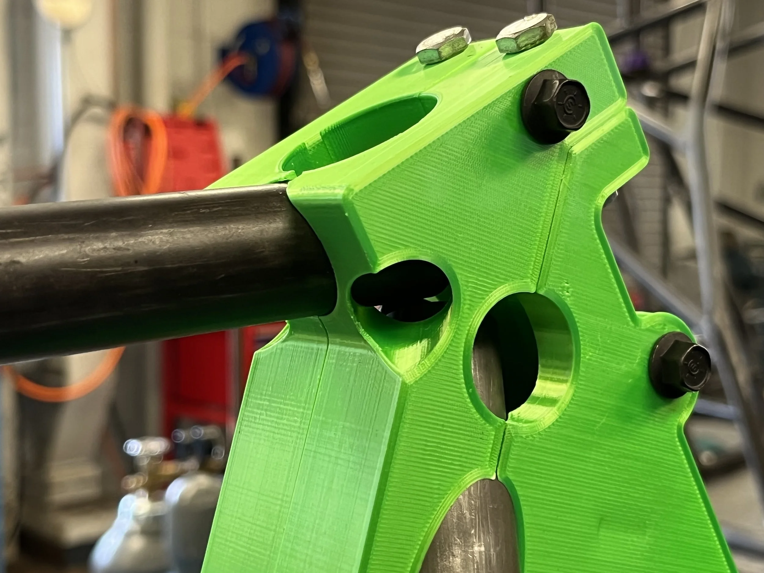
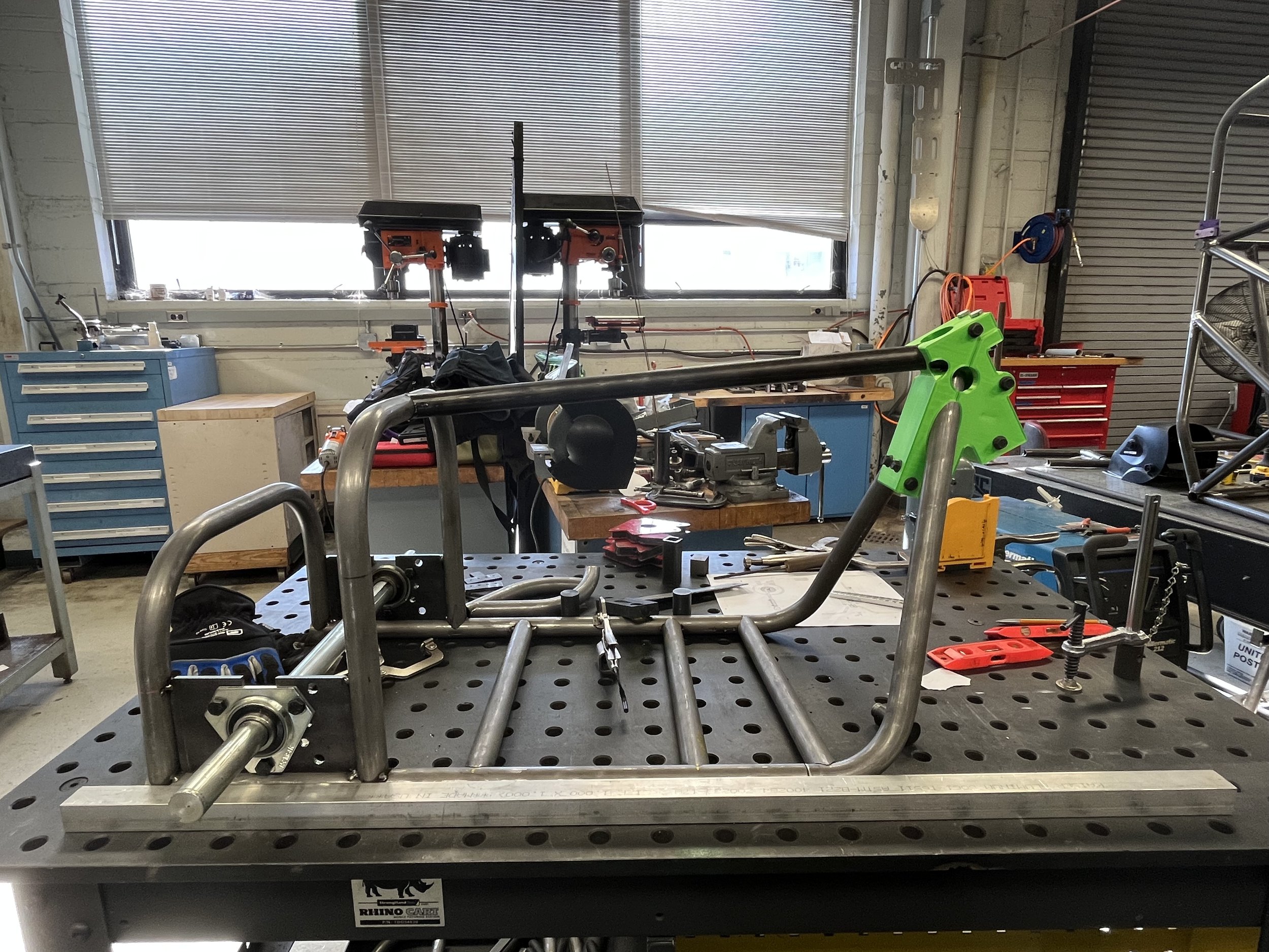
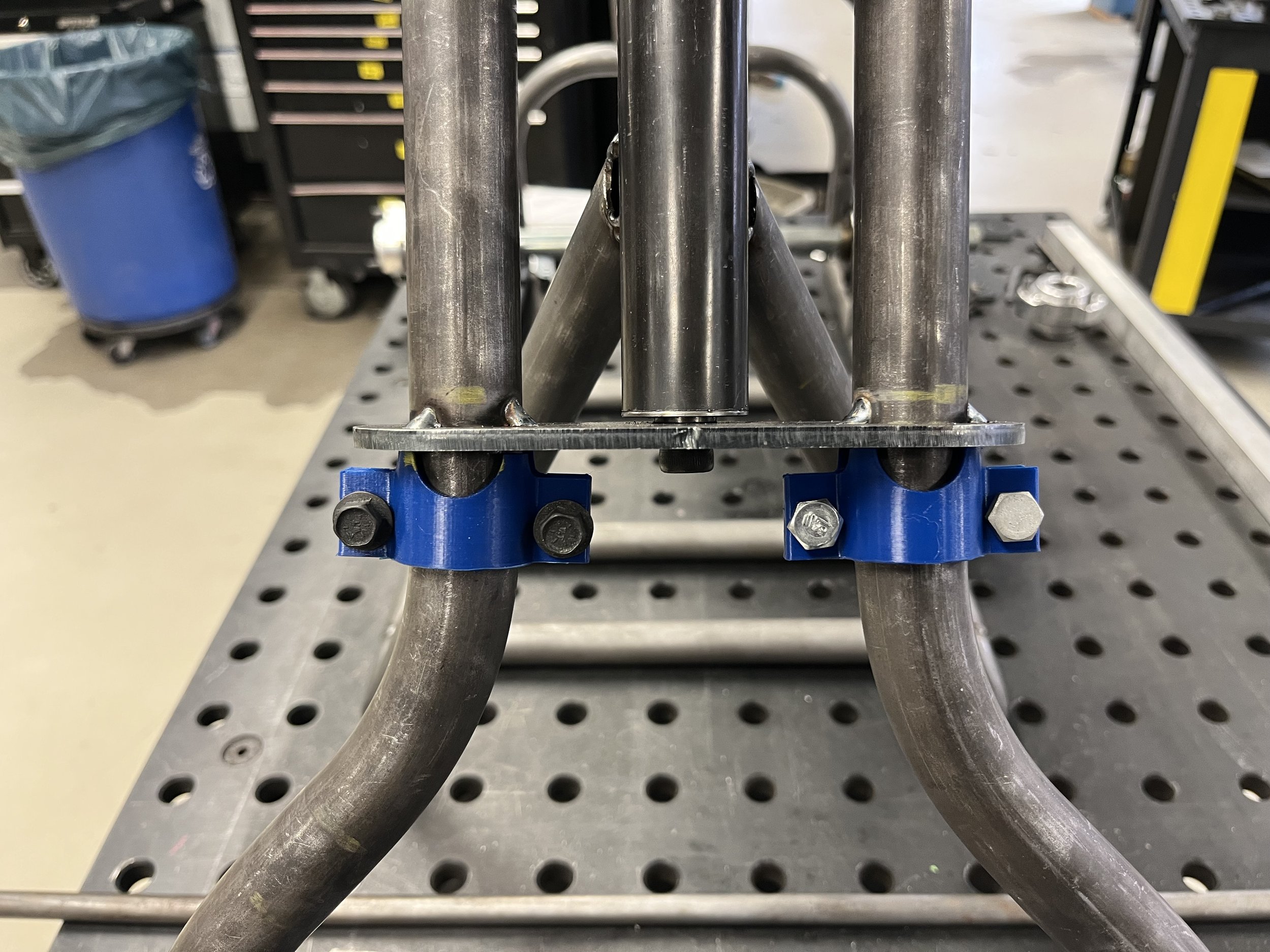
I was also working on ideas to ensure that the tubing at the front of the trike was cut properly so that the head tube can be attached in the correct location. The solution came in the form of a four-piece jig. It allowed me to line things up properly when cutting the tubing at the front of the trike, but it also allowed me to insert the head tube into the jig once the tubing was cut. When designing the jig, I added openings in the areas where the tubing will meet so that I can tack the four pieces of tubing together while the jig was holding them all in place. I made the top tube and with the help of a team member, we cut all the tubing inside the jig and tacked the head tube in place.
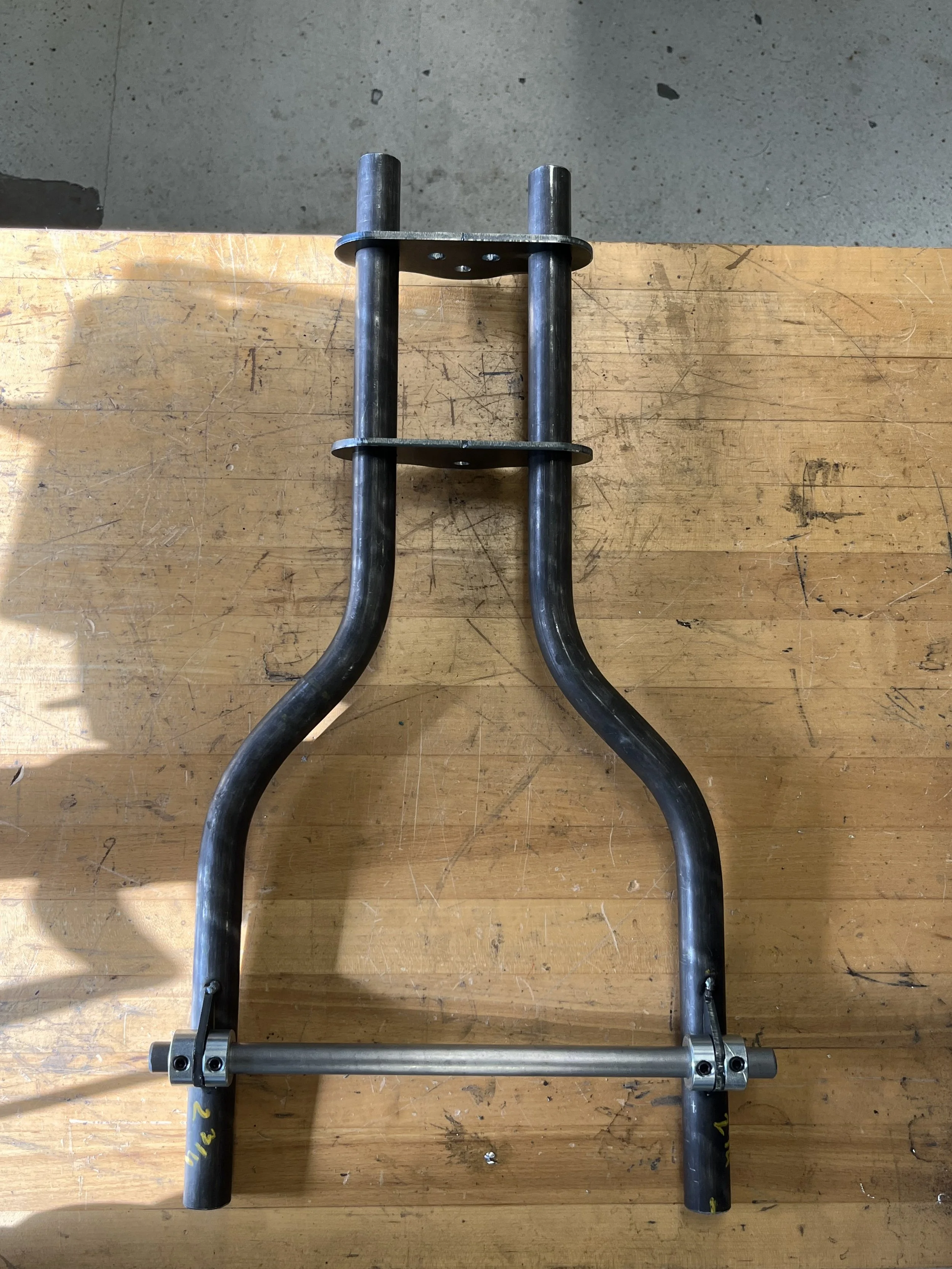
One of the team members used the laser cutter to cut out the re-designed triple clamps for the forks and we continued working on the front forks in preparation for test riding the frame.
Week Five of the Build
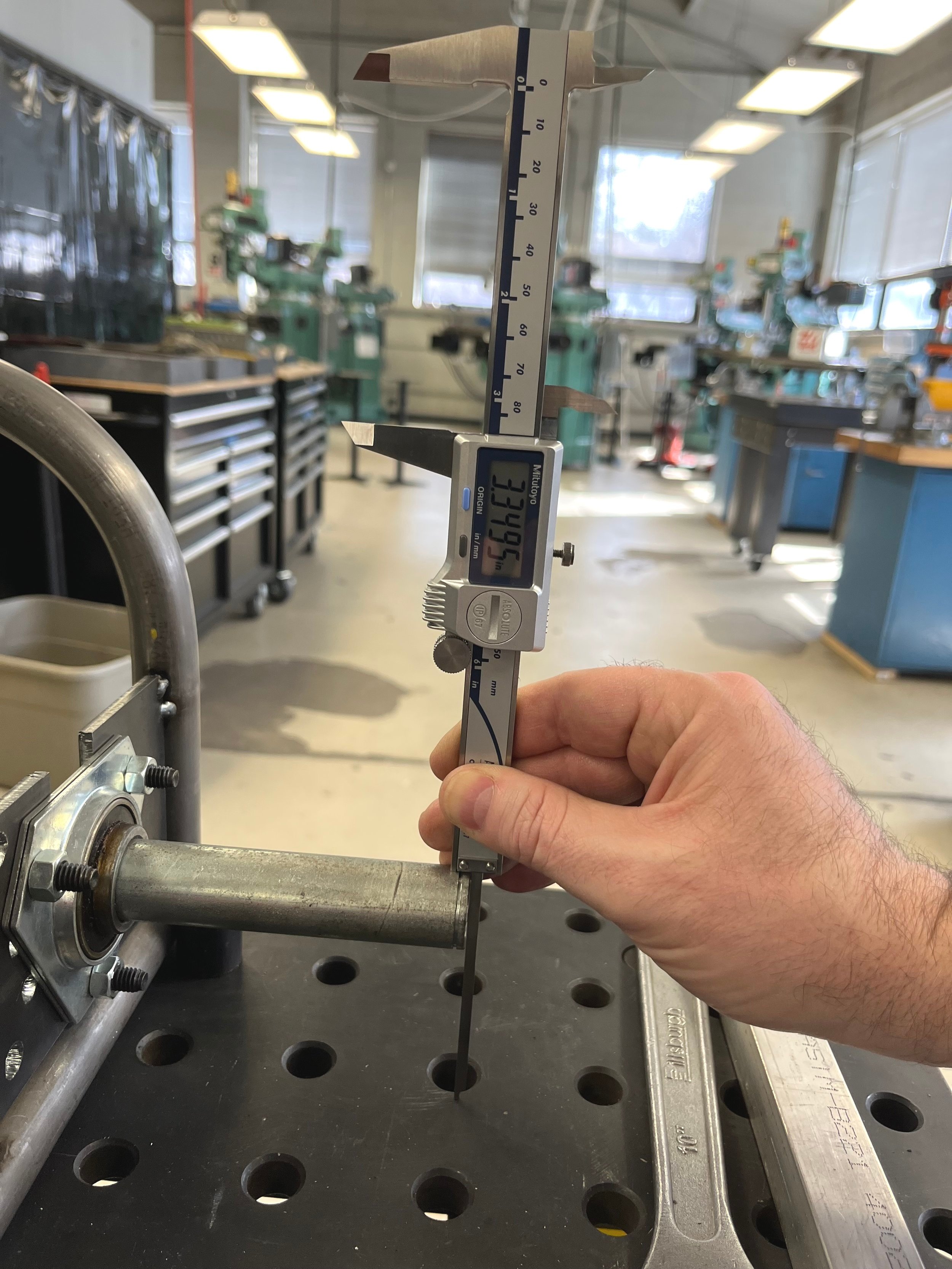
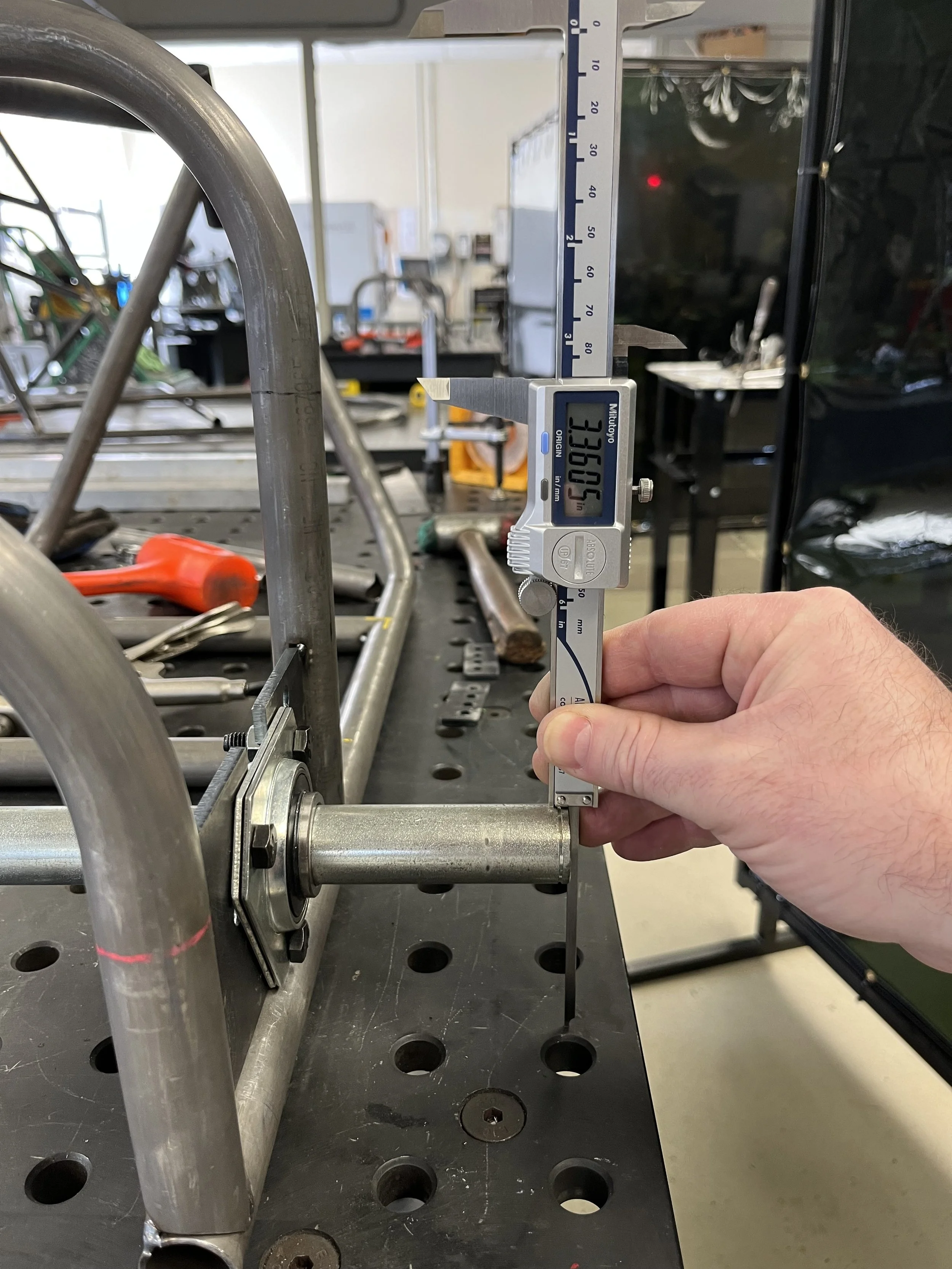
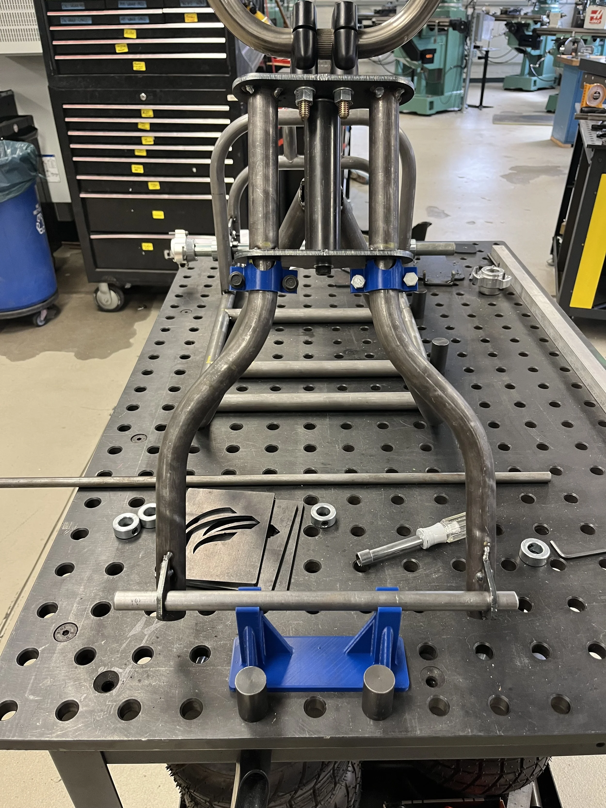
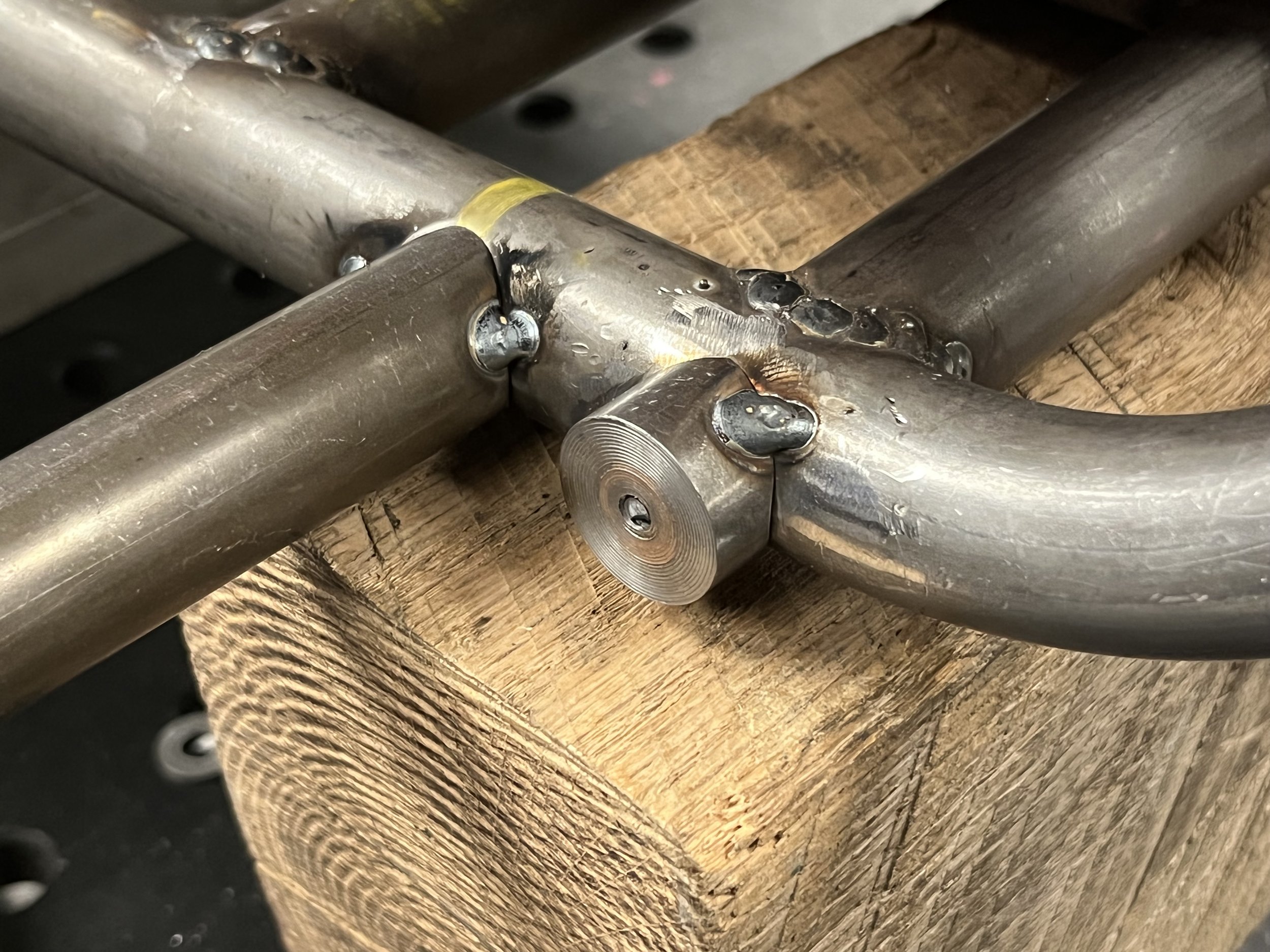
To ensure proper alignment of the forks, I ended up sourcing 5/8” set screw collars at the local hardware store, which allowed me to align the tubing as well as give the bottom half of the forks rigidity. Before I could finish building the forks, I needed to make sure the fork axle was going to be in line with the rear axle so that the trike can ride level. The rear axle was level within 0.011 inches from side to side. I took these measurements in preparation for 3D printing a jig that would elevate the front forks to their proper height for manufacturing.
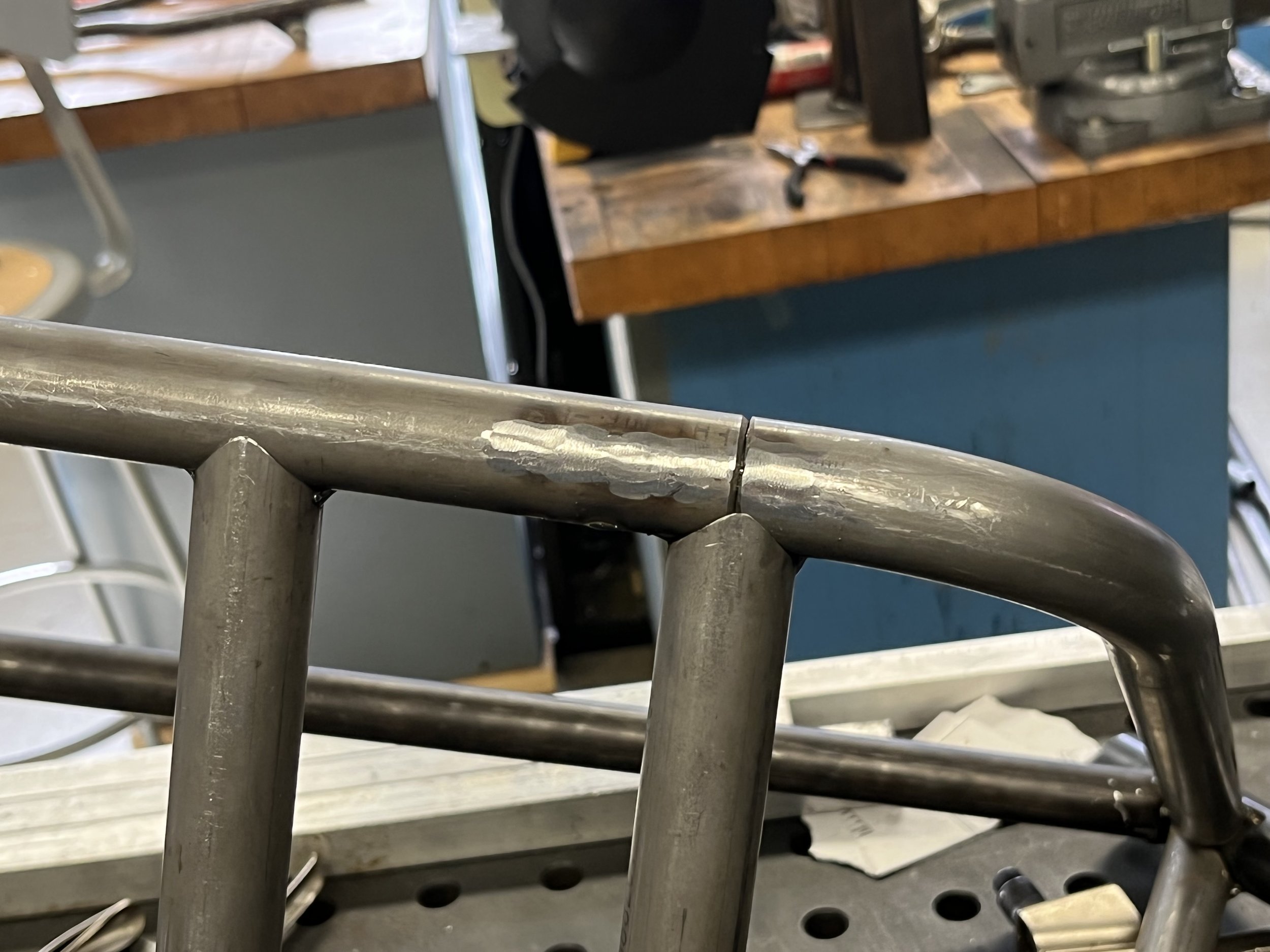
I added the final engine cross brace, and welded and cleaned few areas of the frame in preparation for the rolling test.
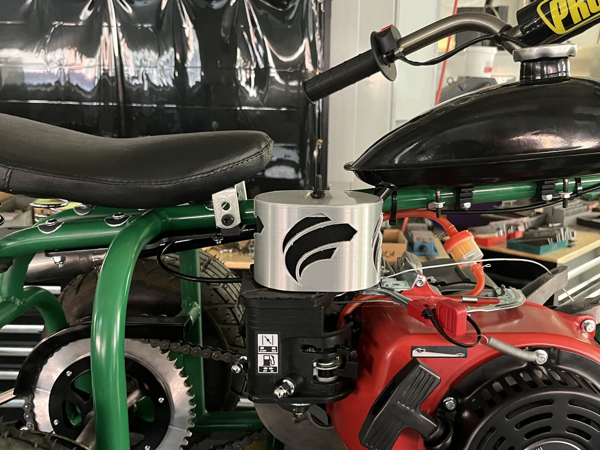
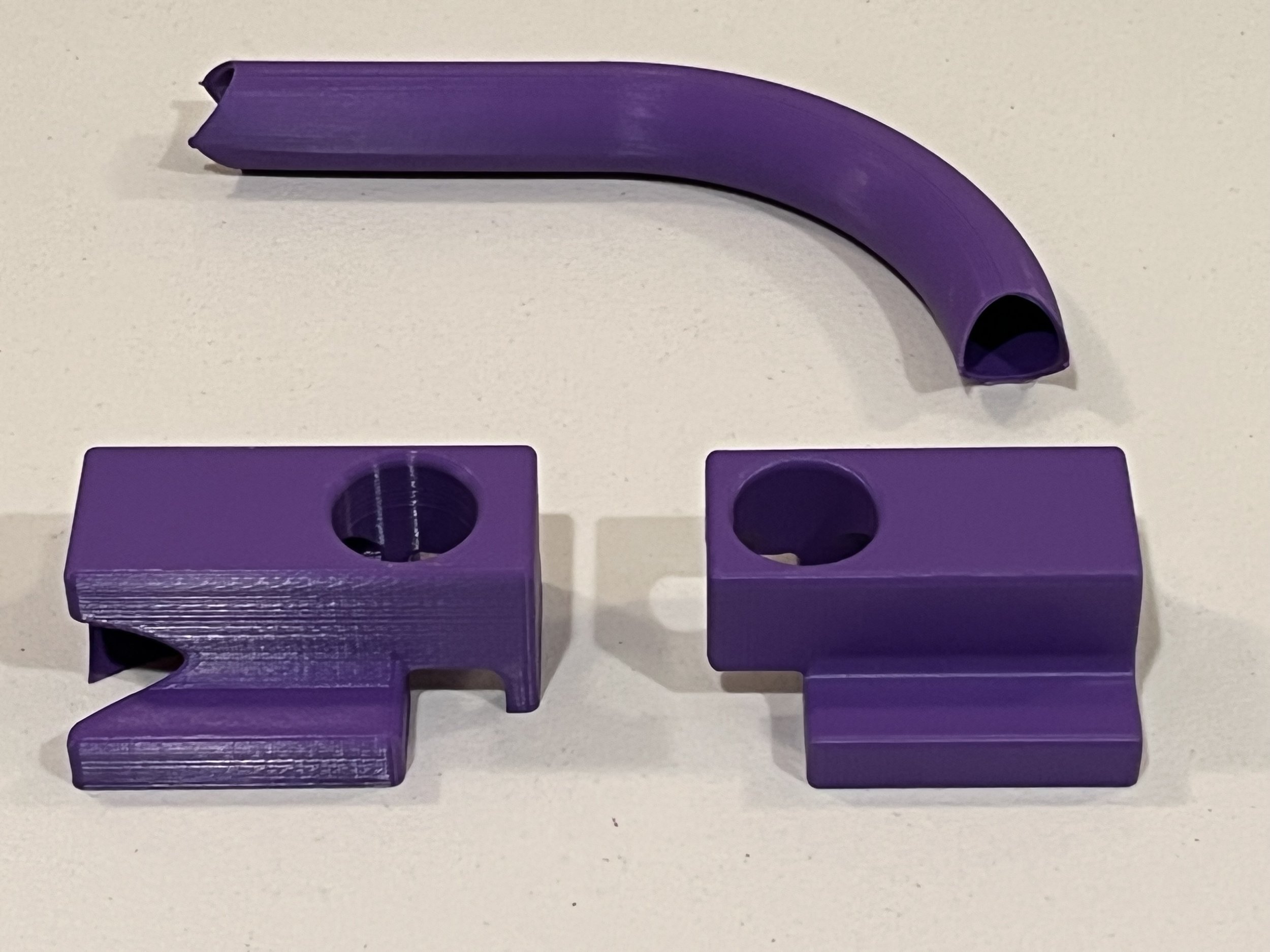
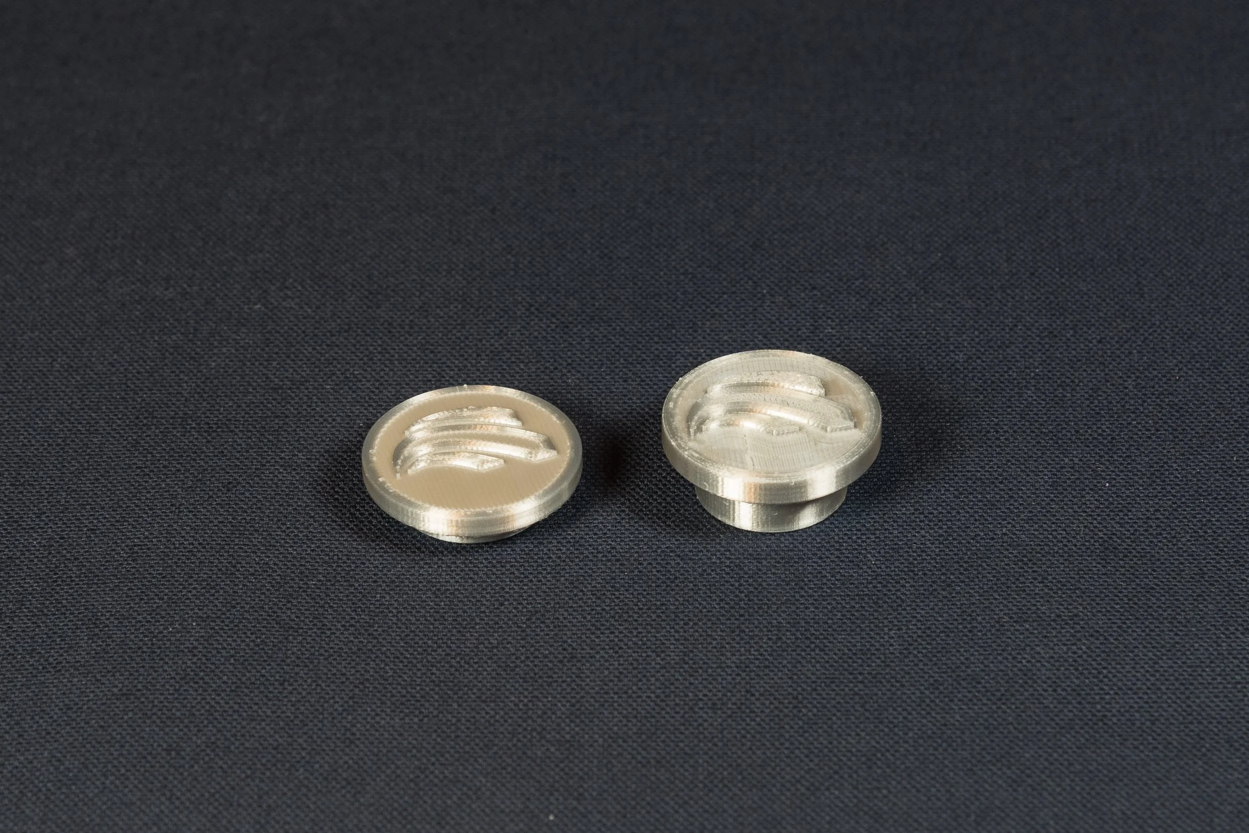
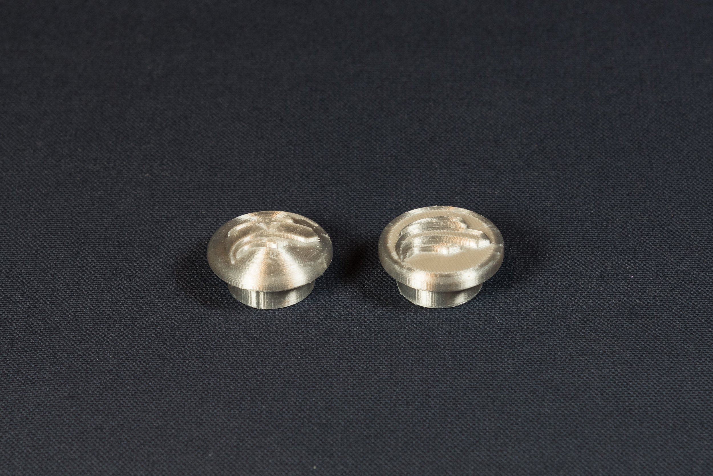
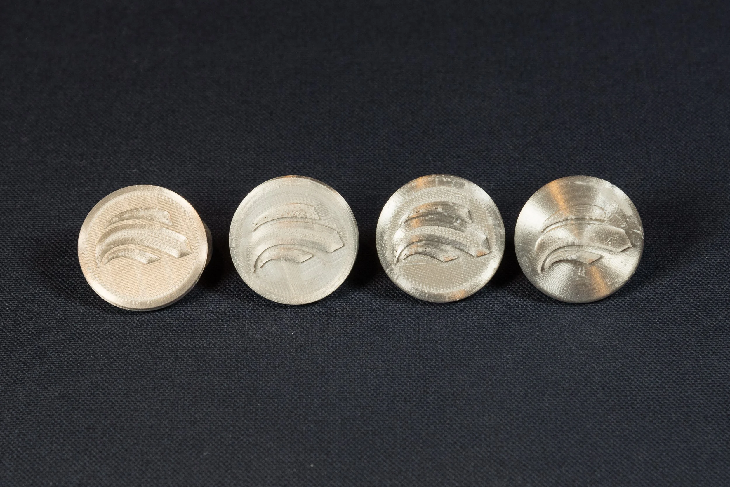
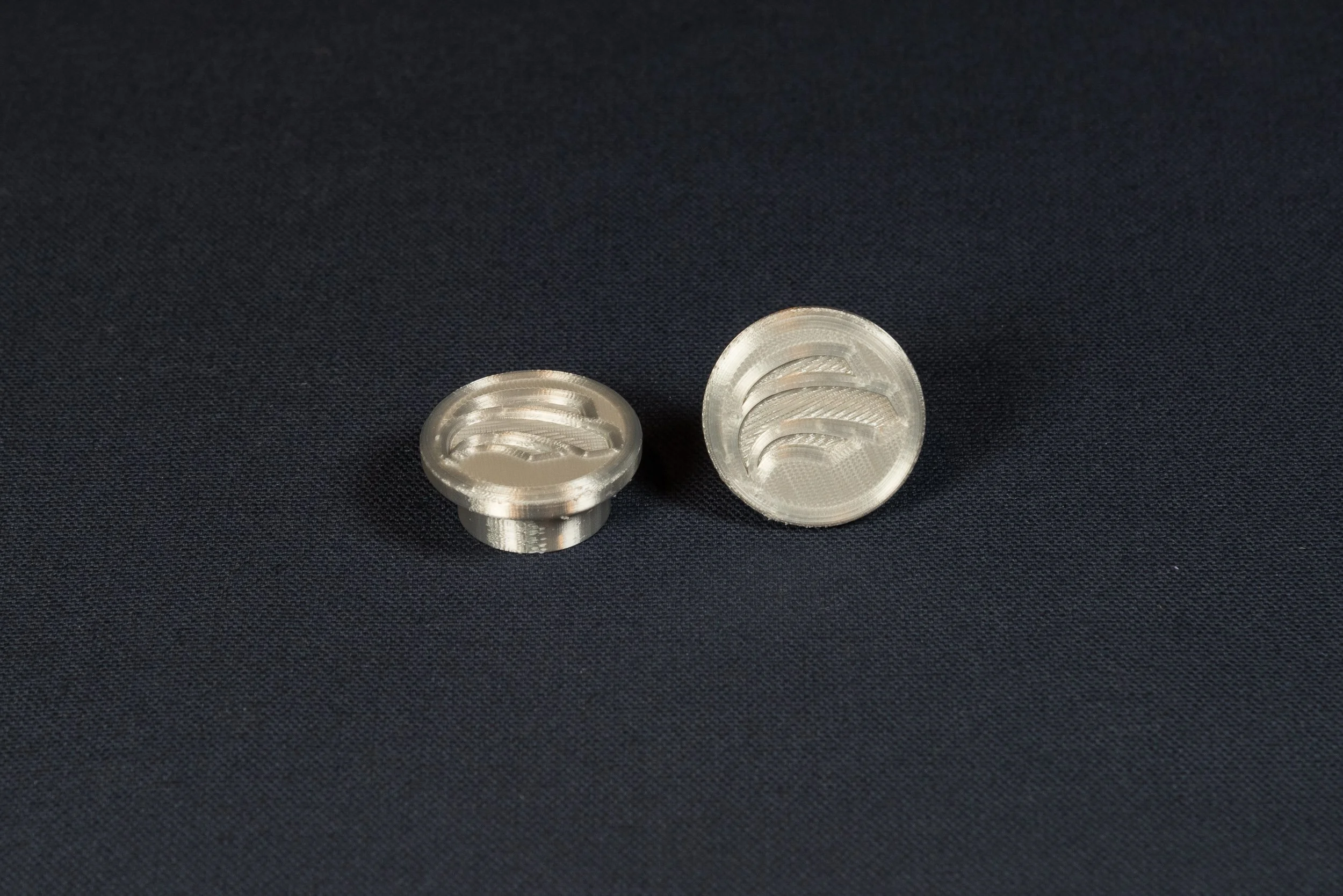
Between classes my attention turned to 3D printing the front fork jig and the collets which will be used in the manufacturing the triple clamps. I also ran some tests on the button that will cover the opening in the fork tubes, but given the inconsistent surface finish, these will need to be 3D printed with an SLA printer.
Manufacturing the forks turned out to be more challenging than expected. The 3D printed jig worked perfectly and gave us one of two consistent reference points as we worked through the challenges. The handlebar risers that were supplied did not match the ones on the purchase order and we ran into hardware clearance issues. This meant that I had to re-design the triple clamps.
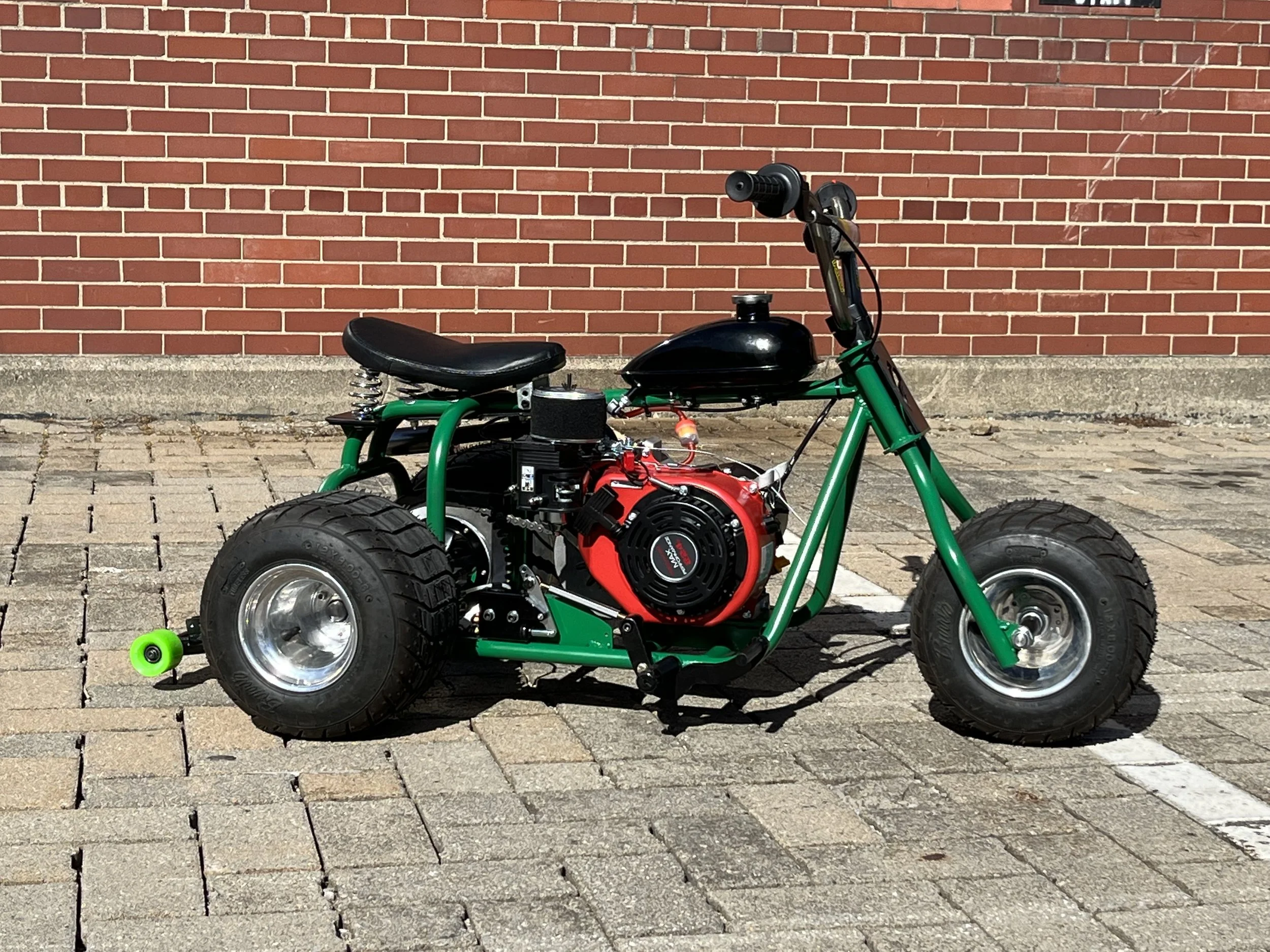
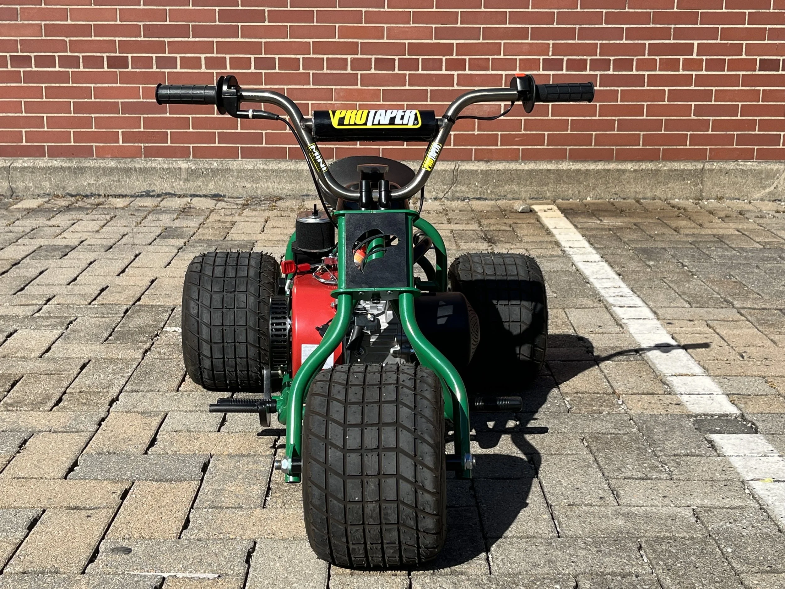
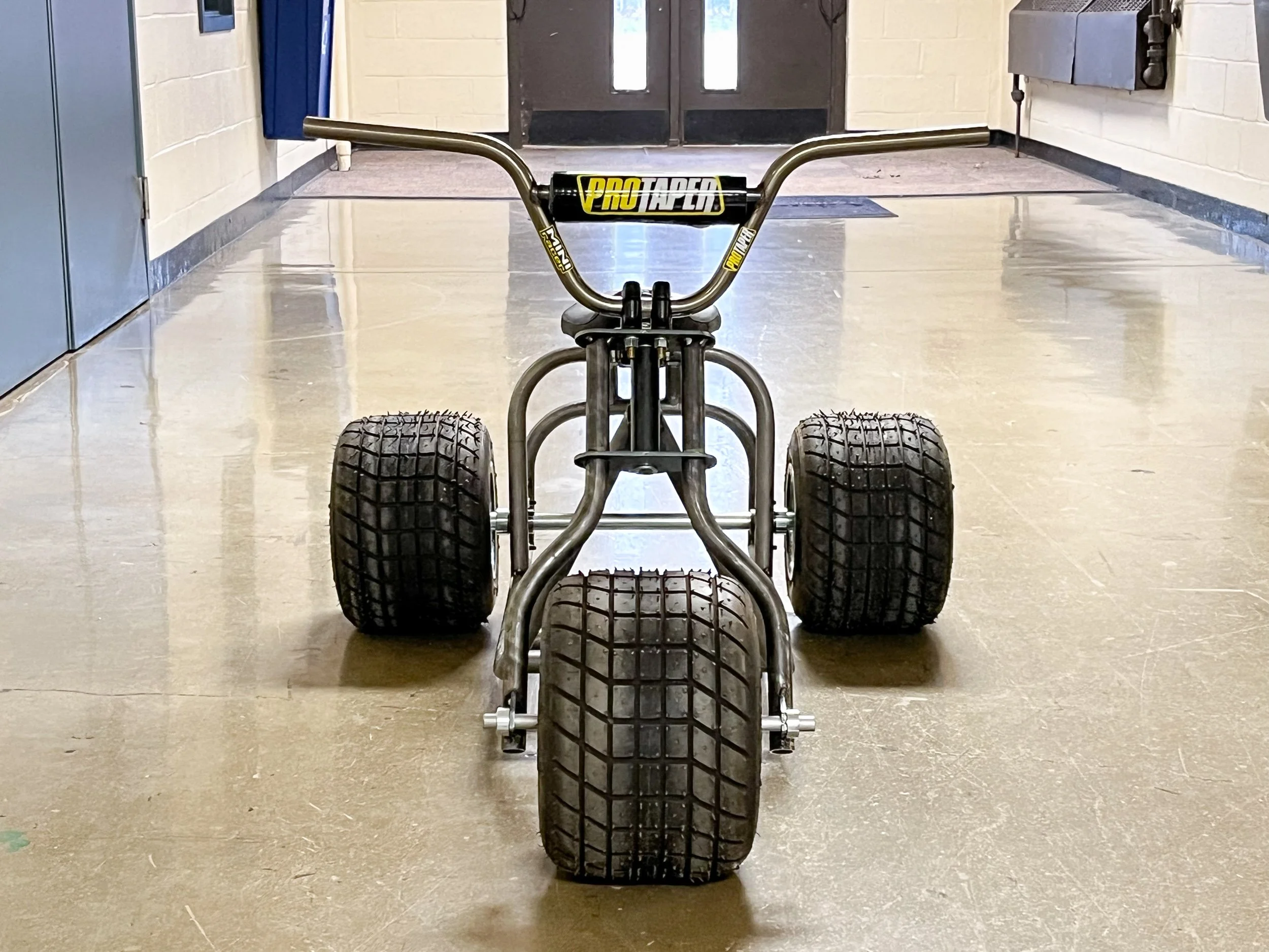
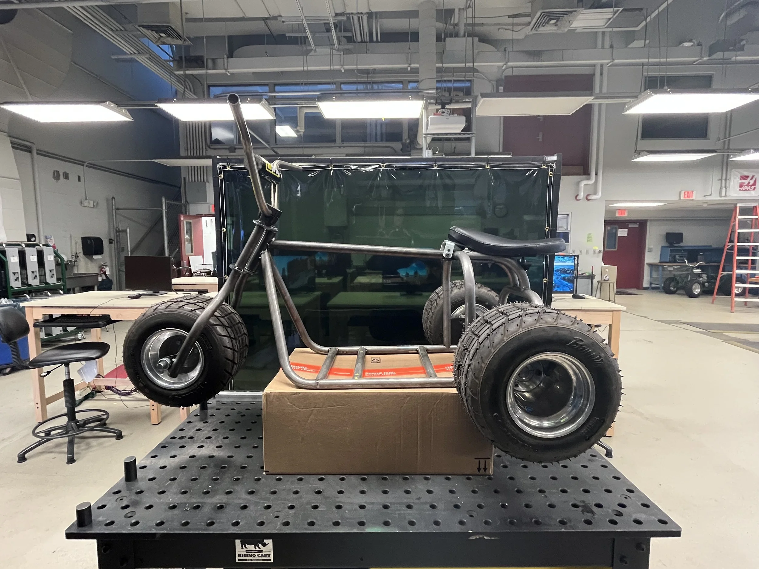
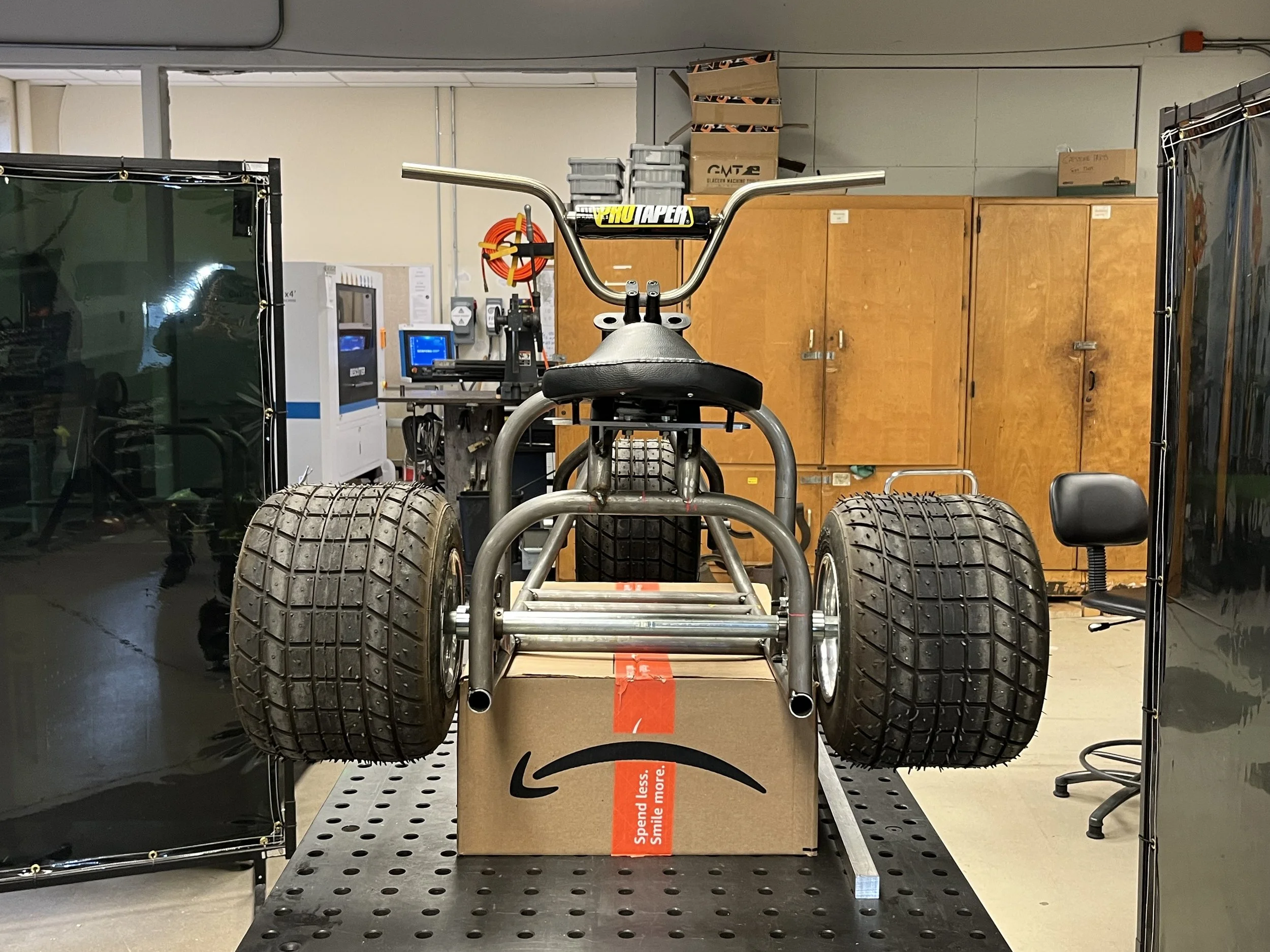
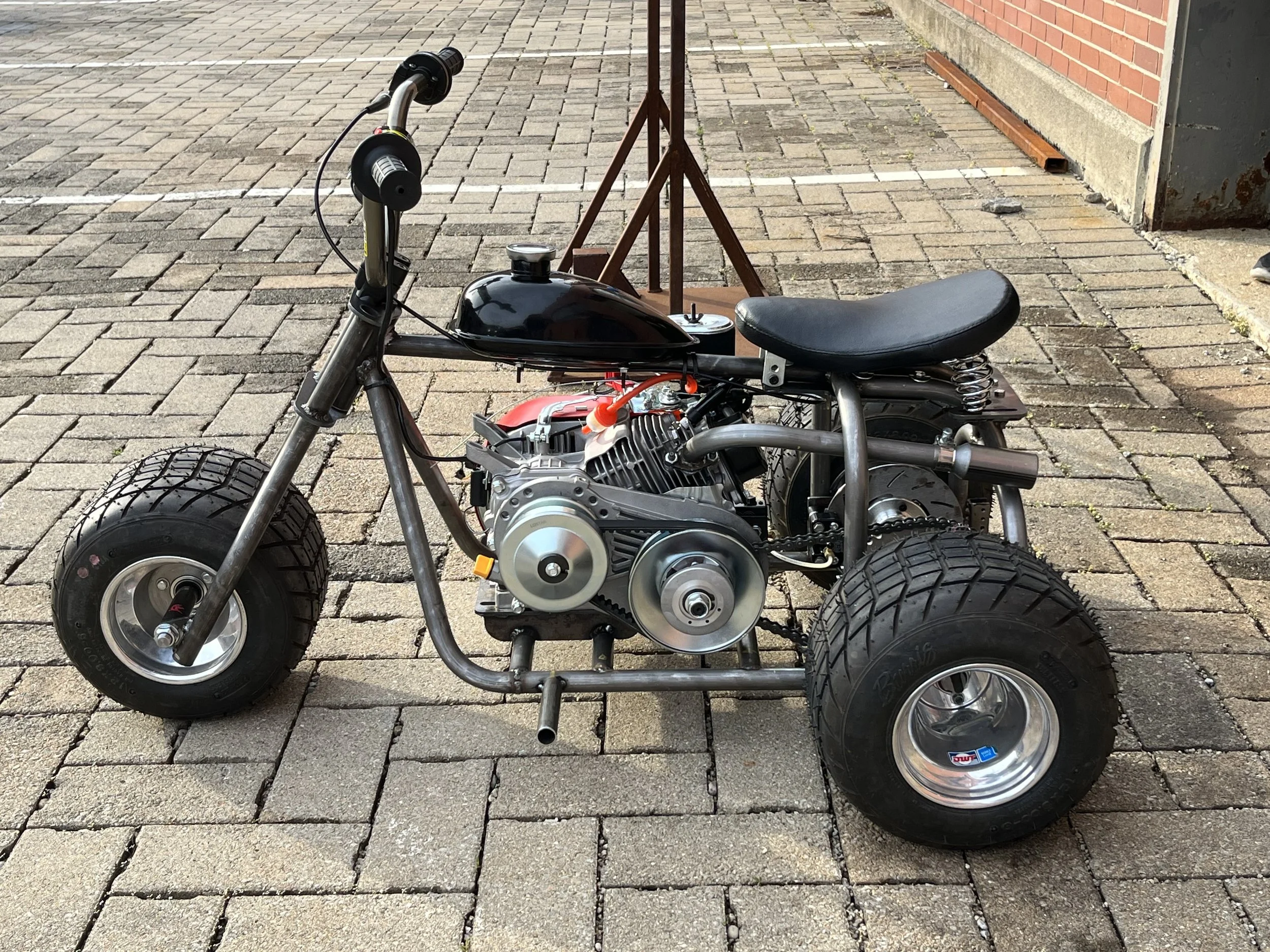
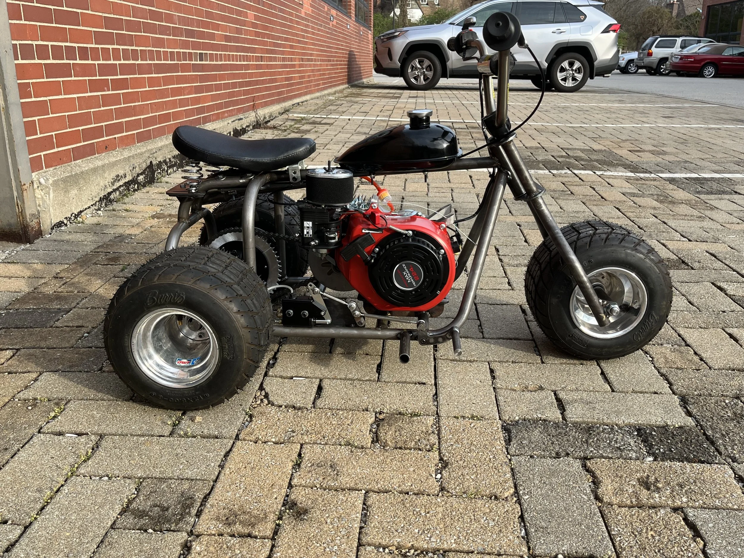
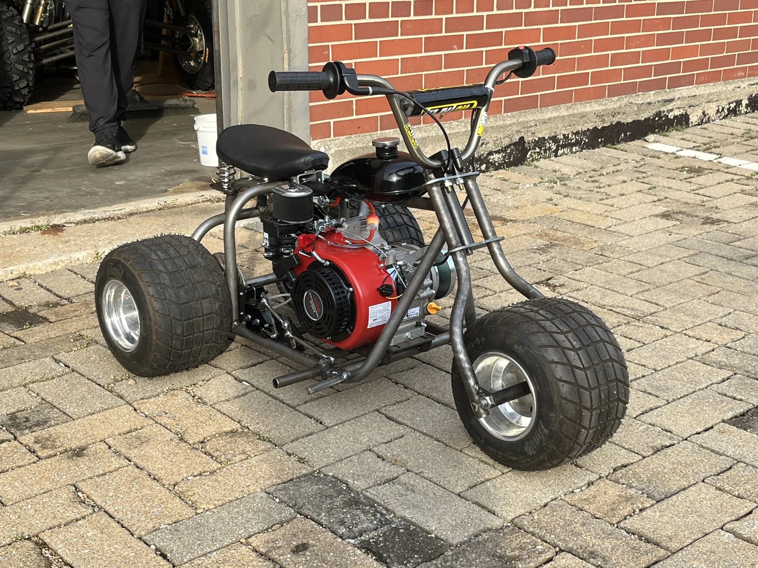
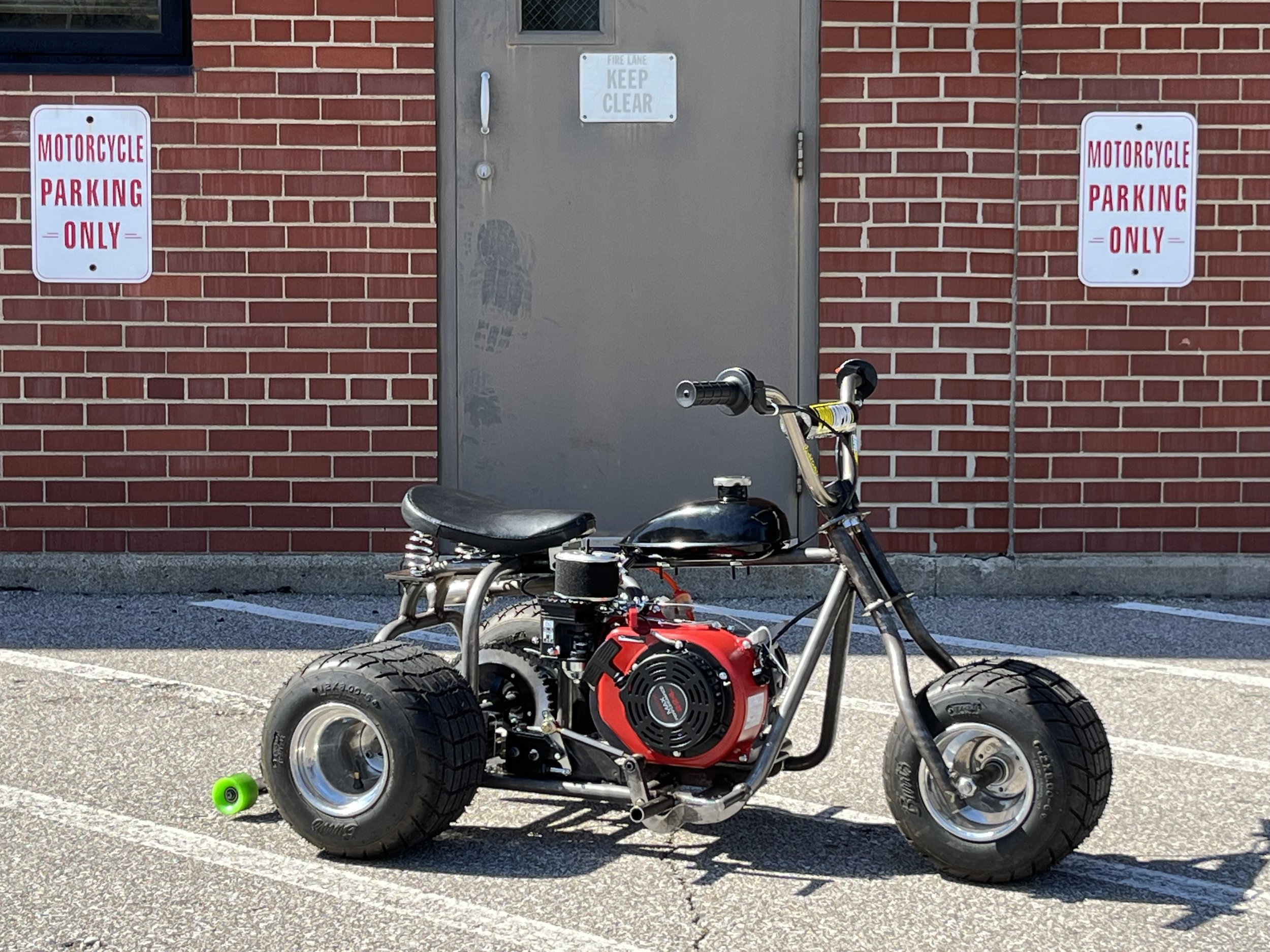
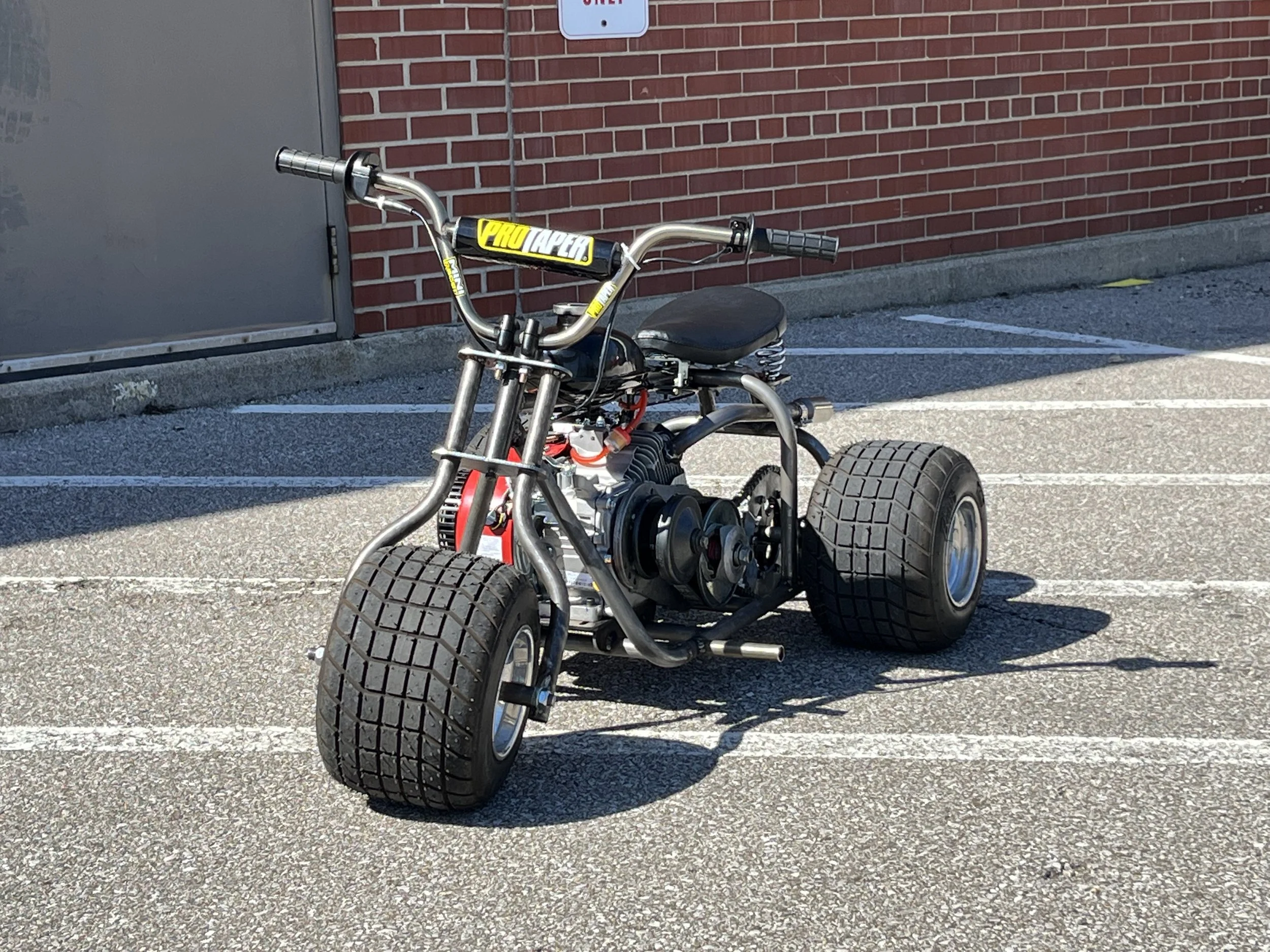
Once the forks and the seat base were manufactured, everyone on the team descended on the trike to help with the assembly and complete it before the end of class. The trike was lowered to the ground with 15 minutes to spare and everyone on the team got a chance to take a photo with the rolling frame.
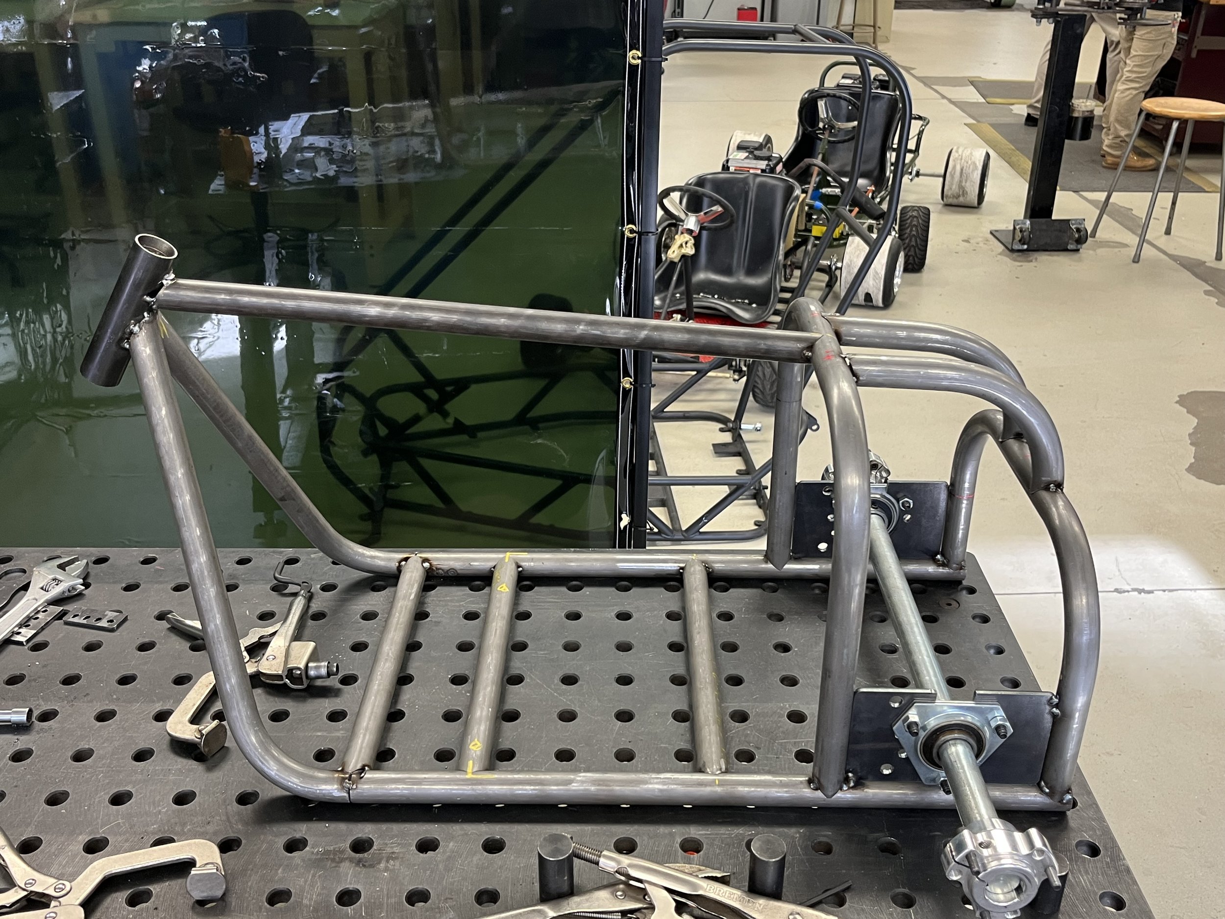
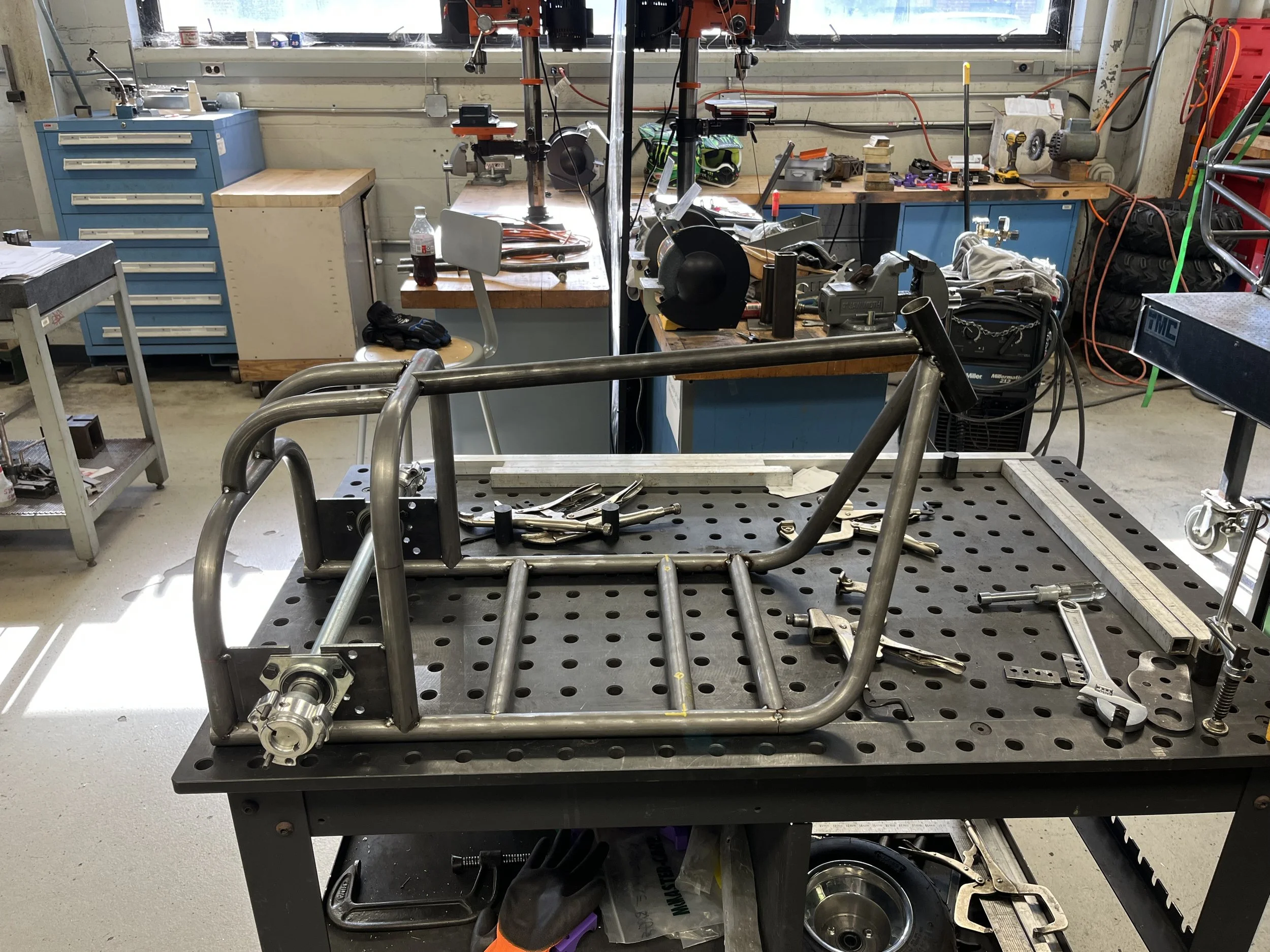
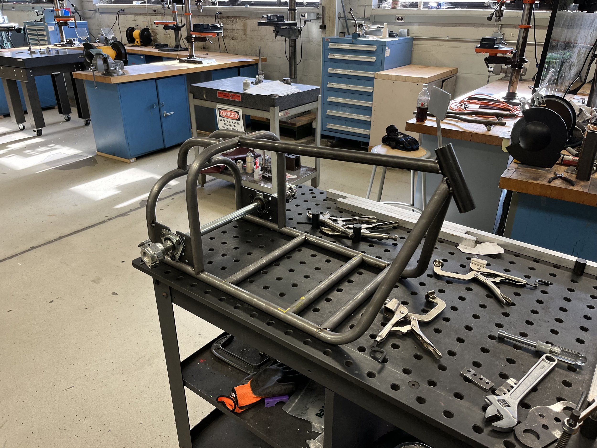
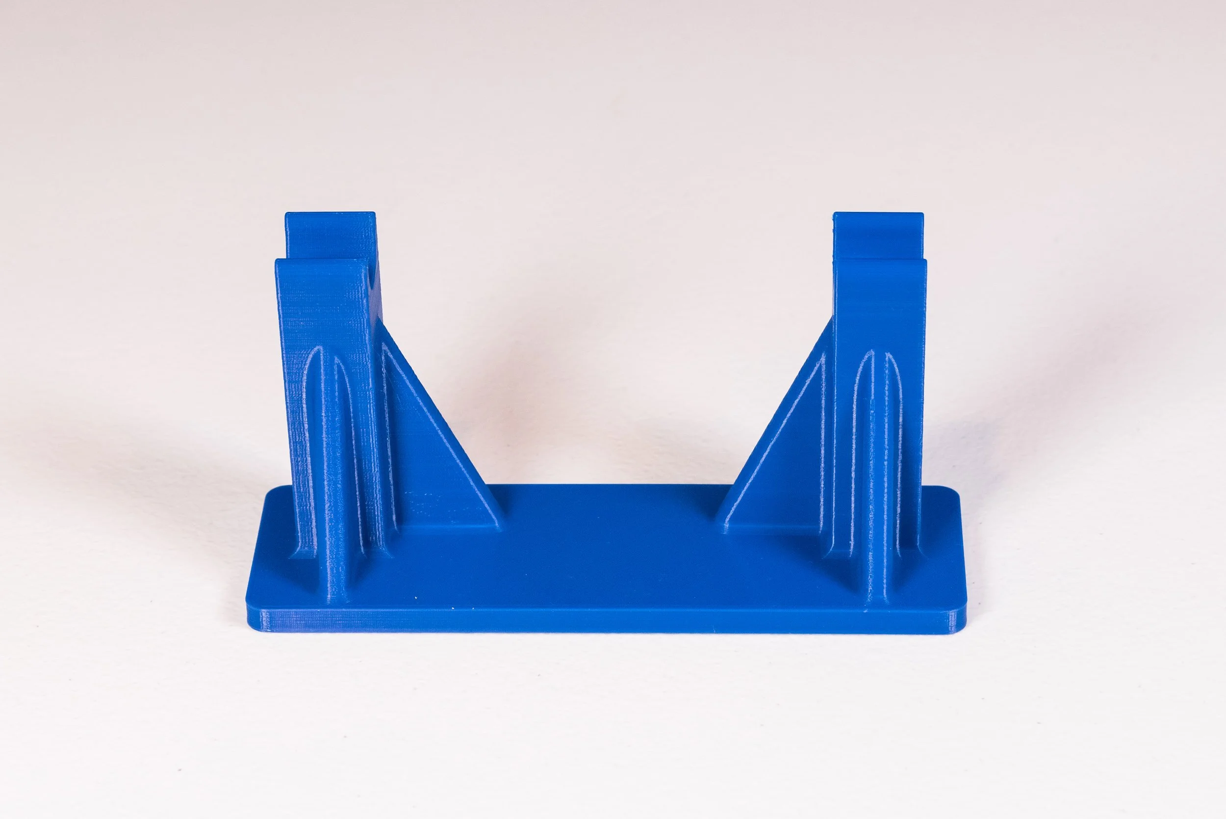
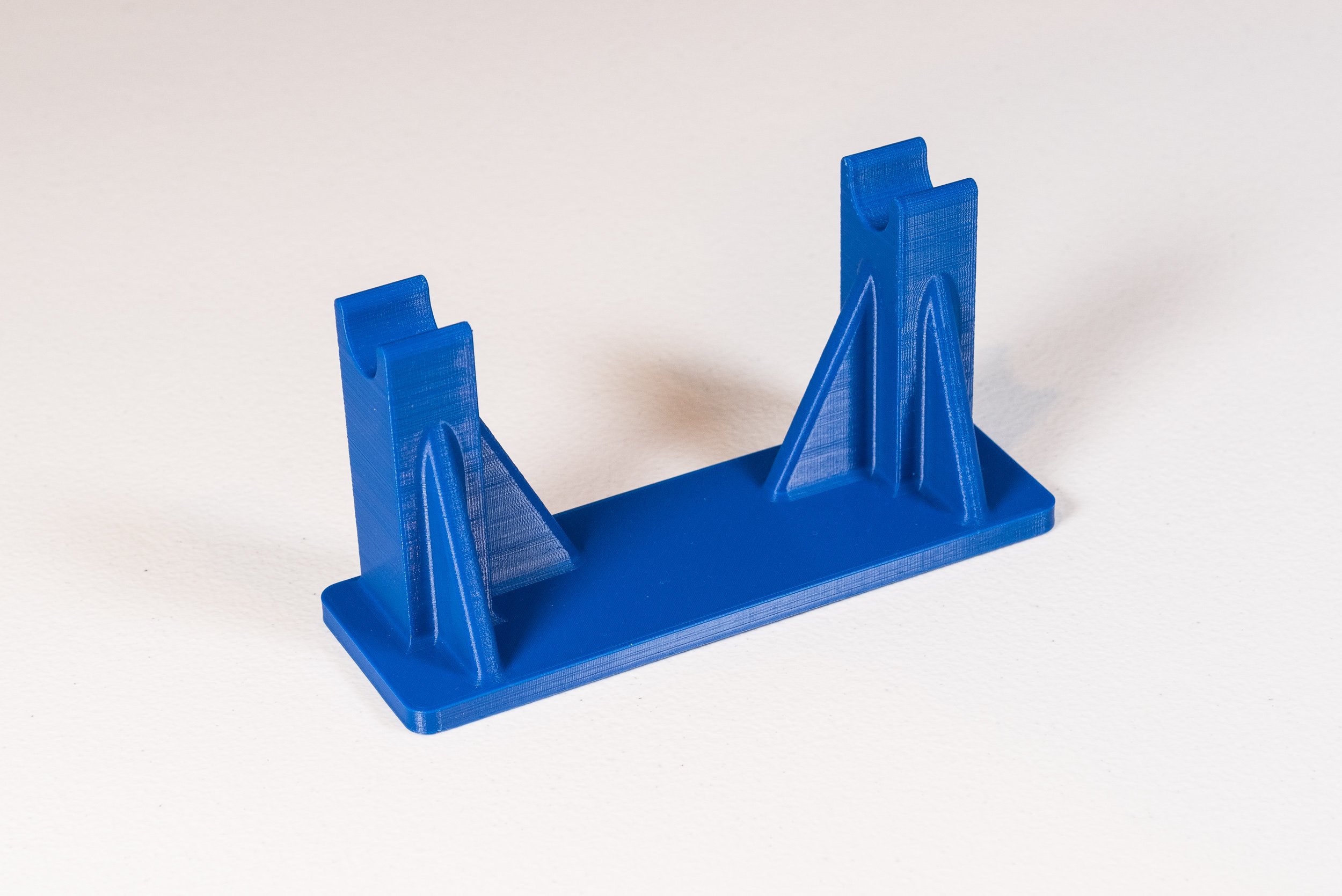
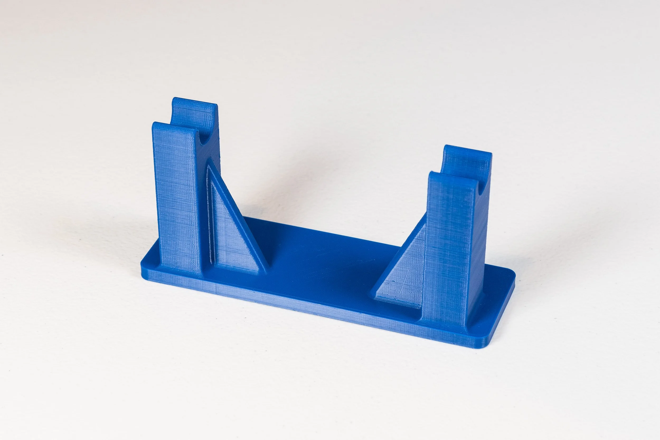
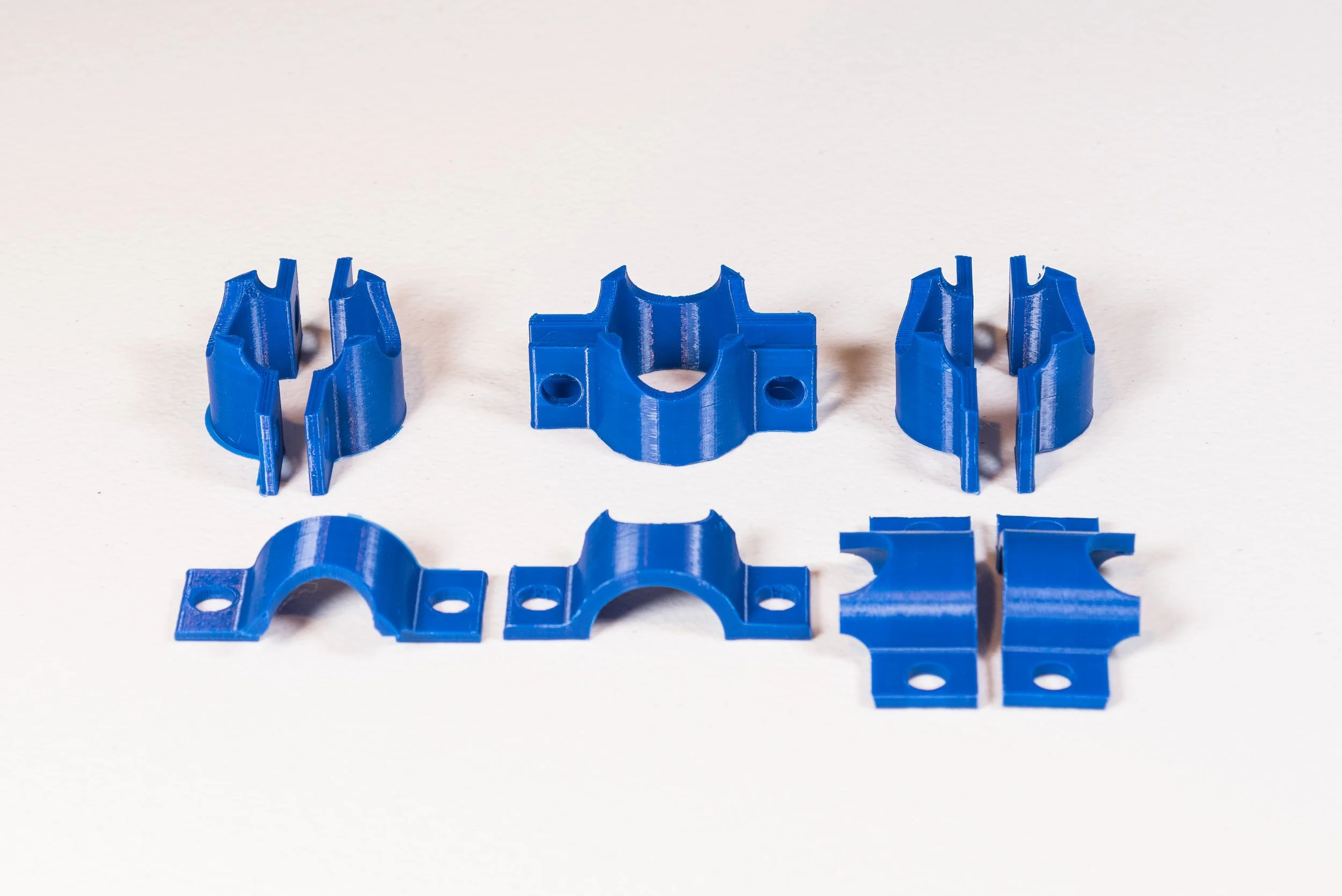
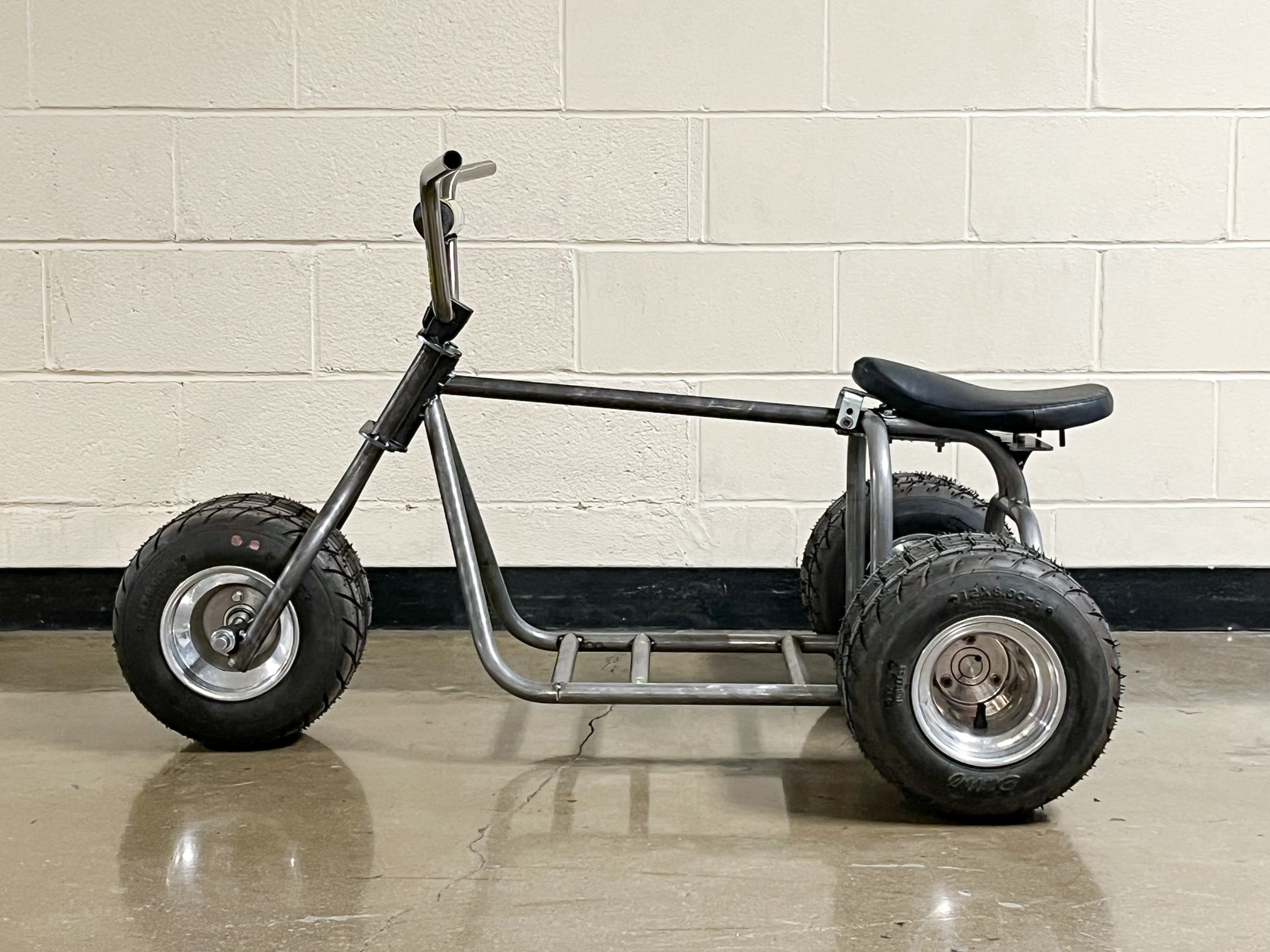
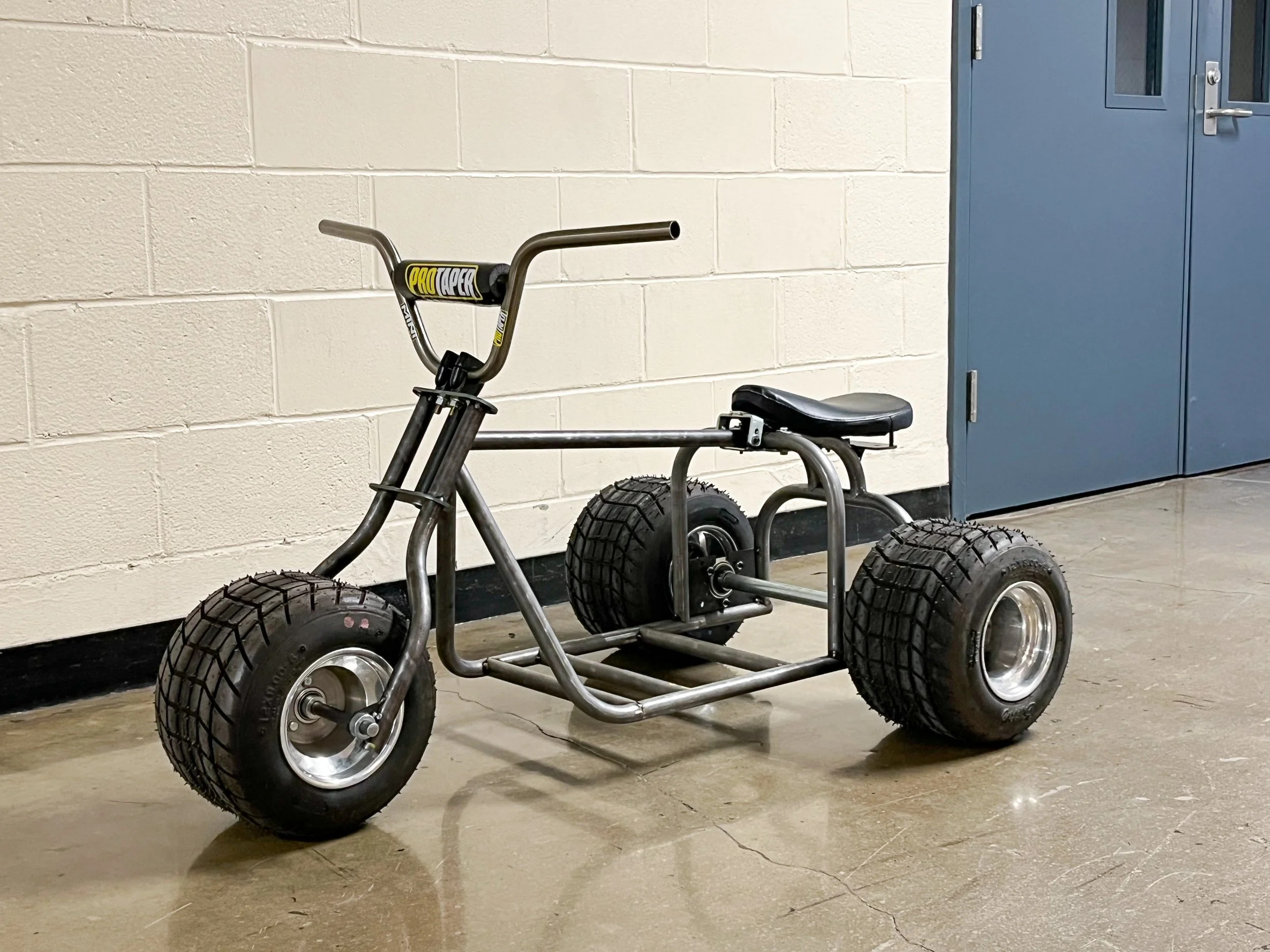
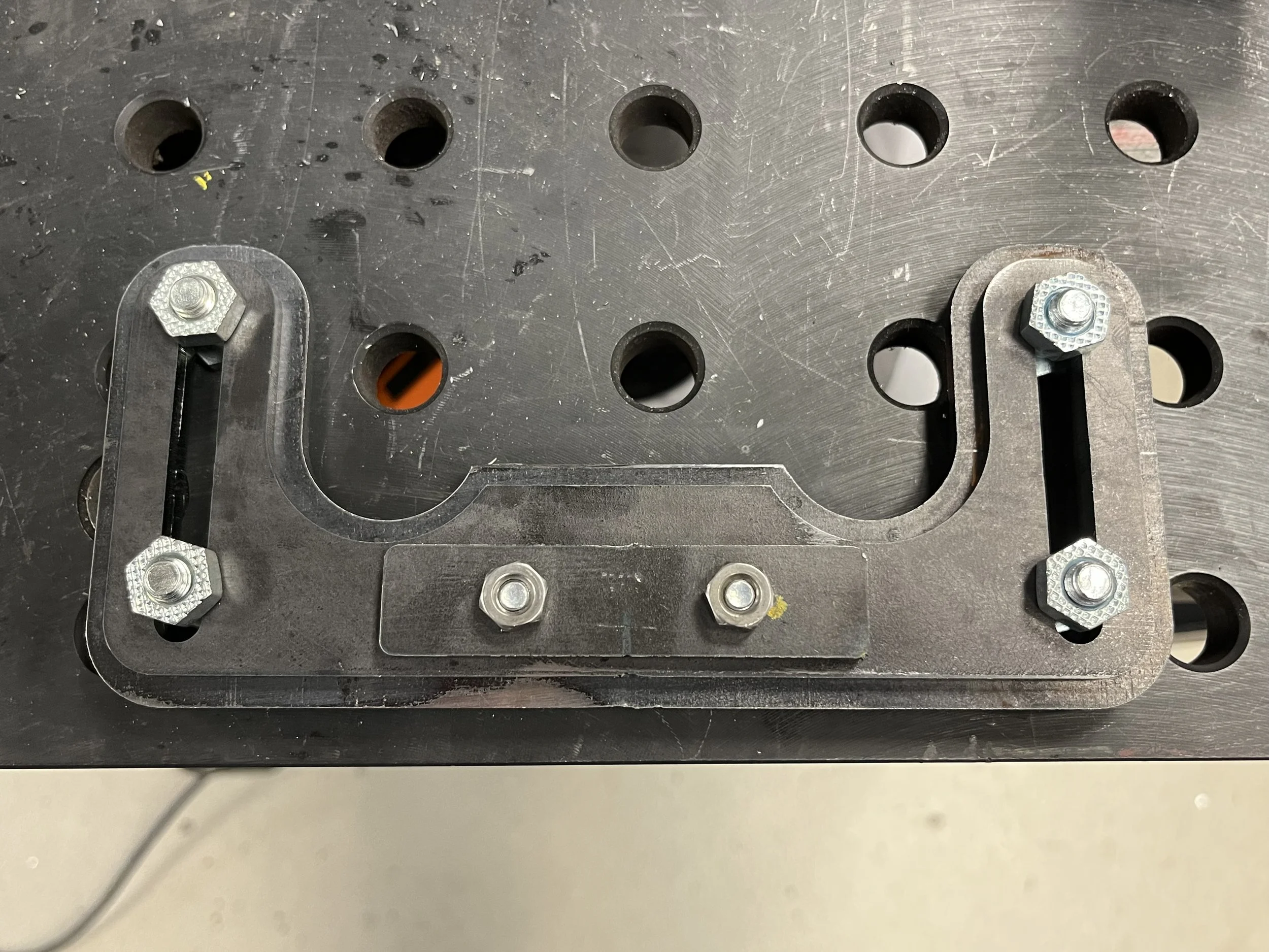
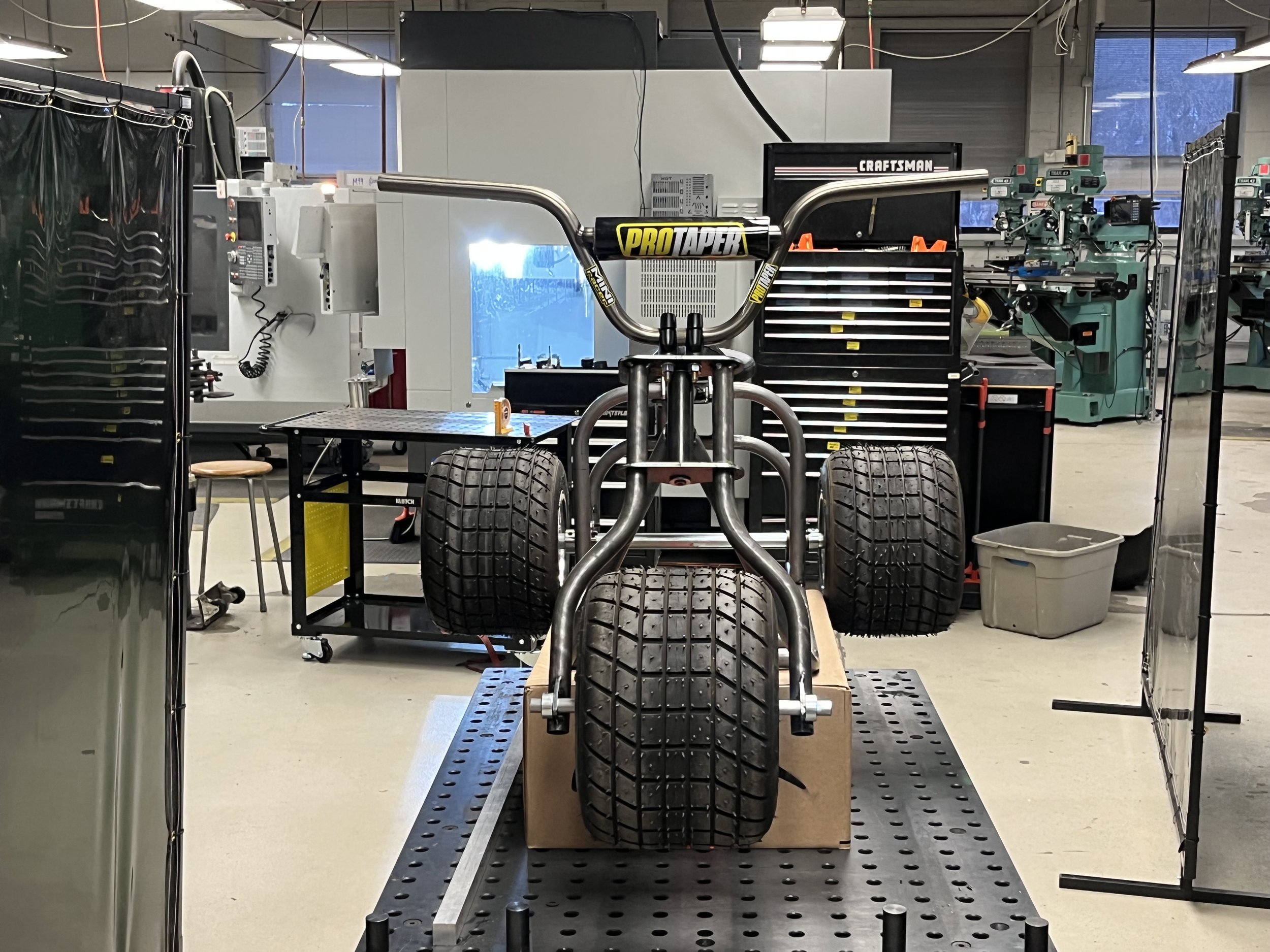
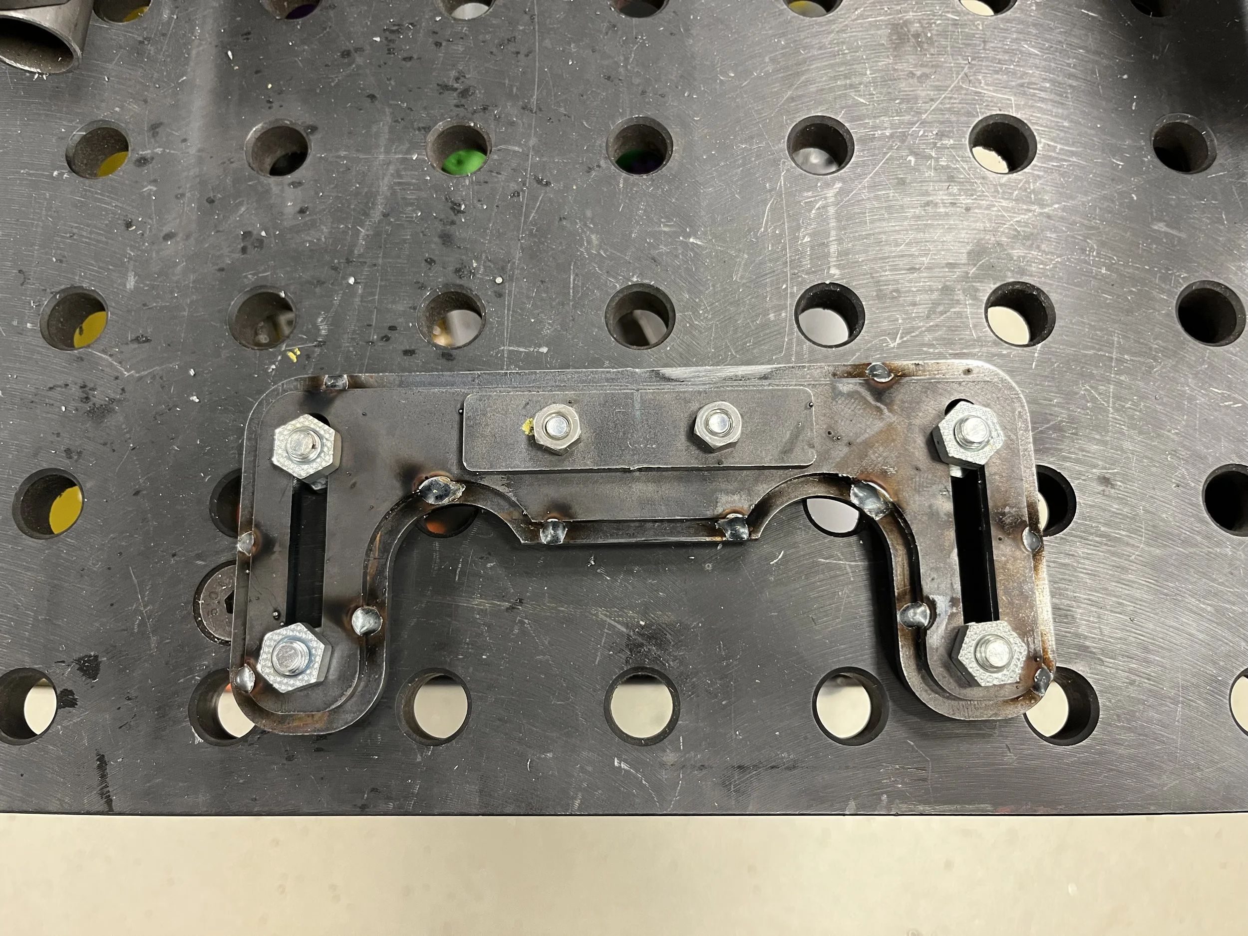
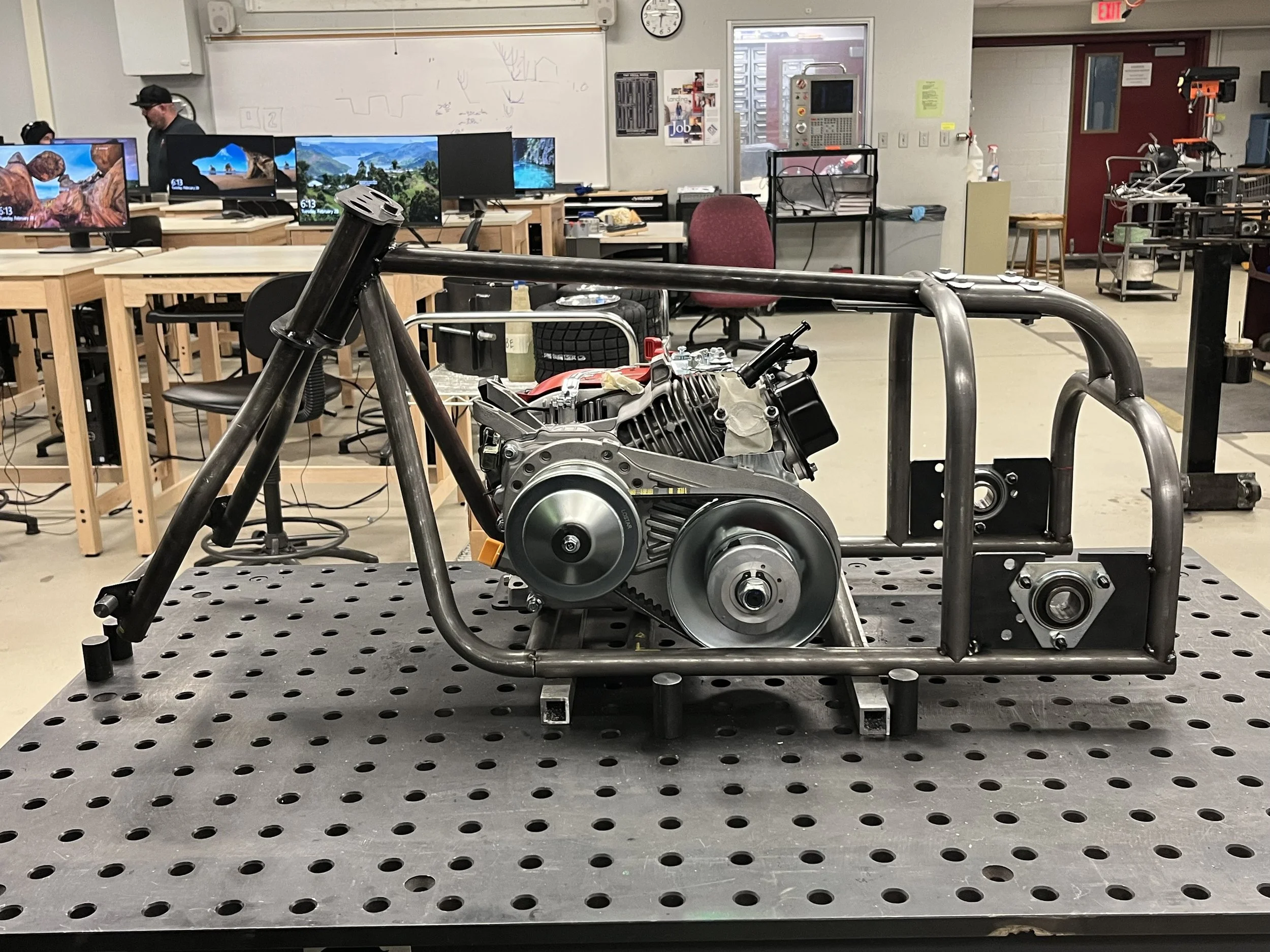
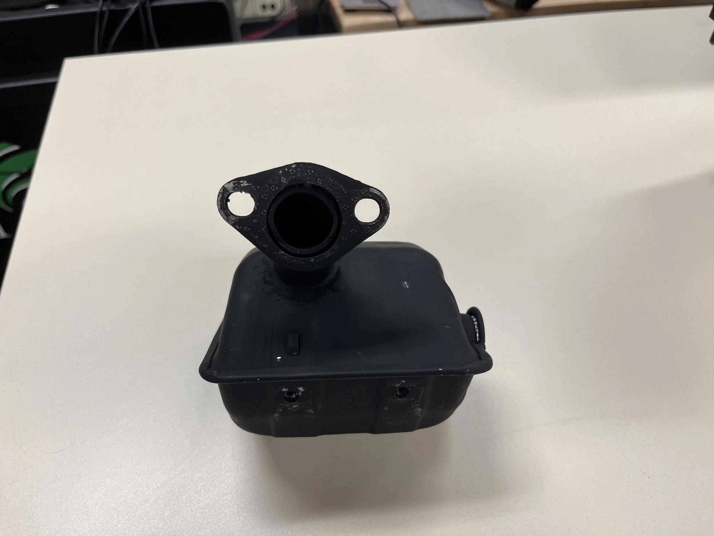
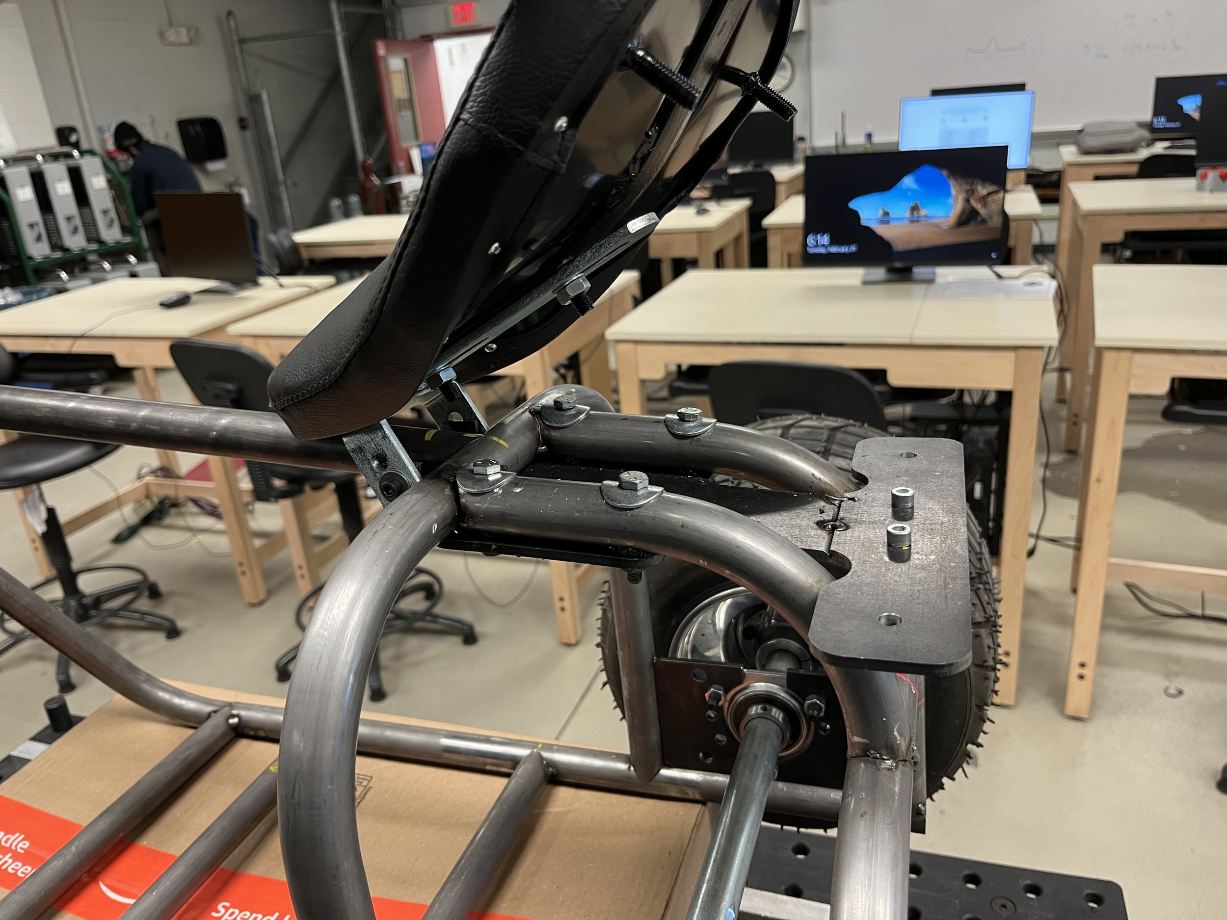
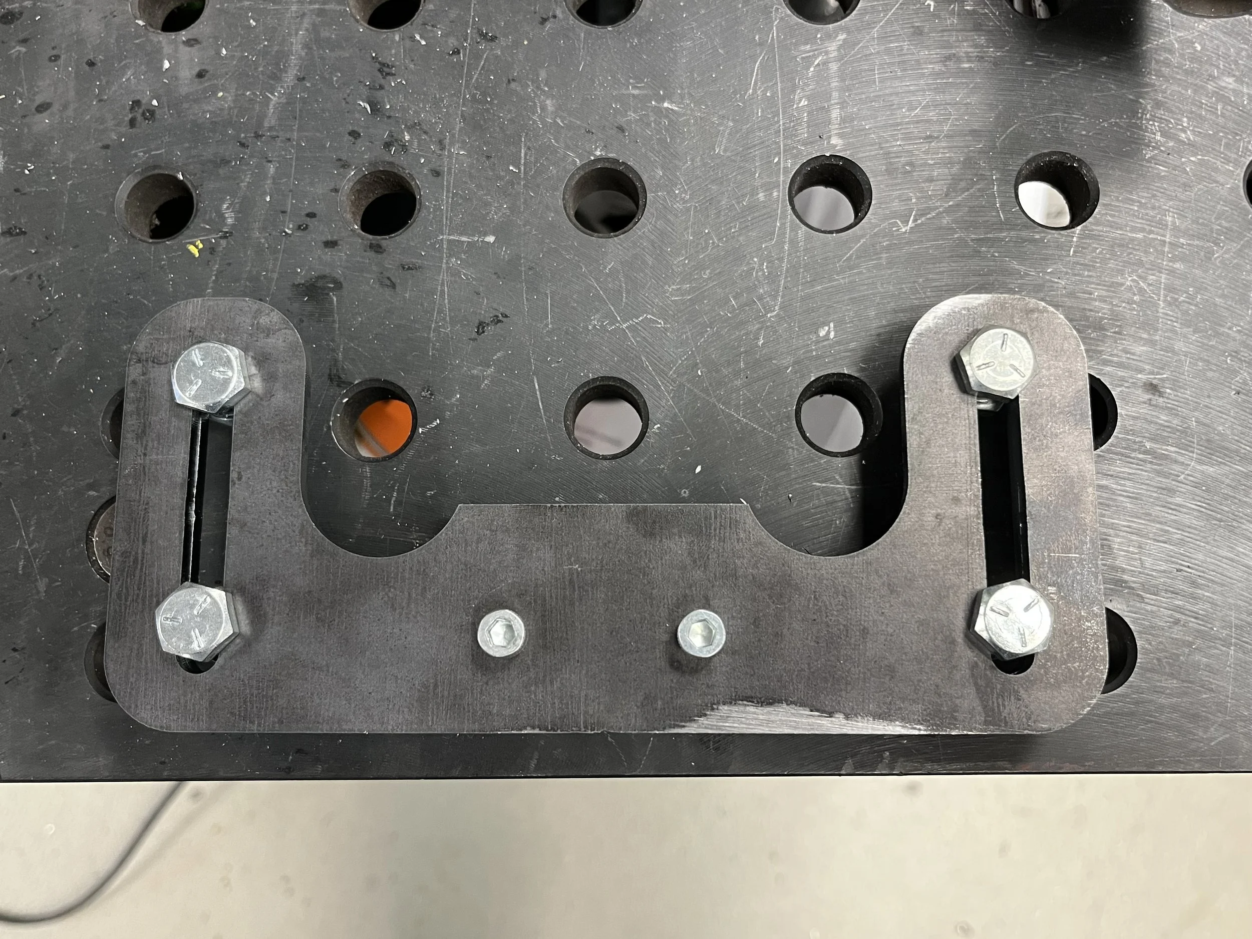
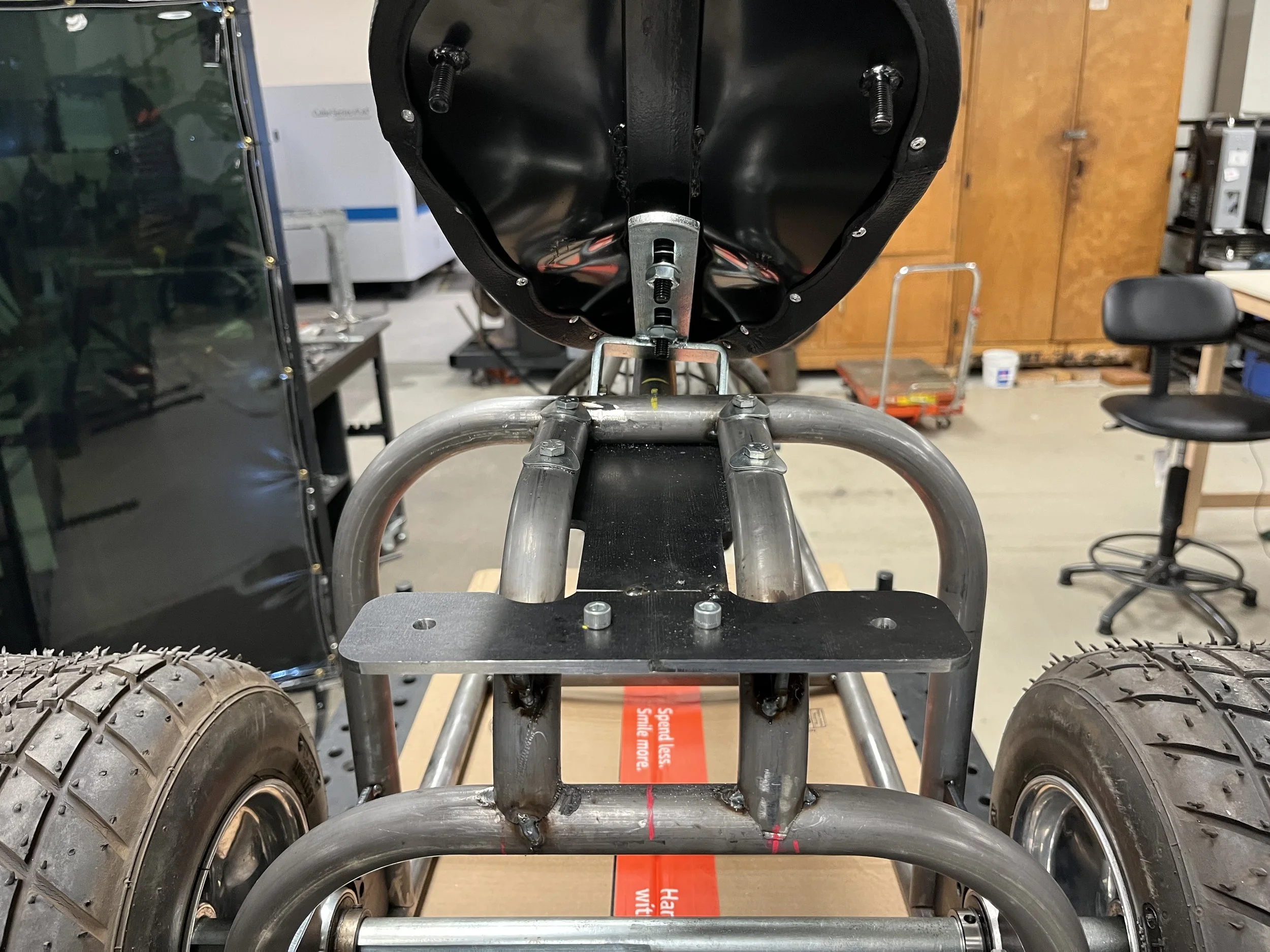
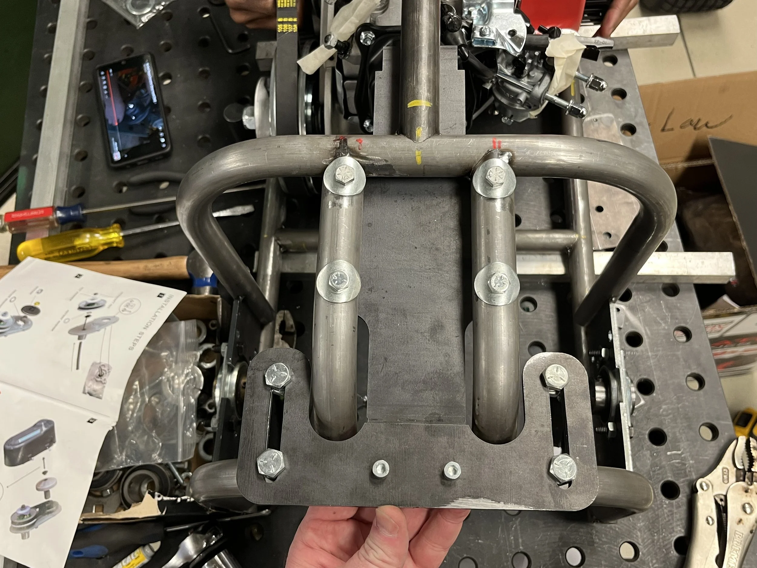
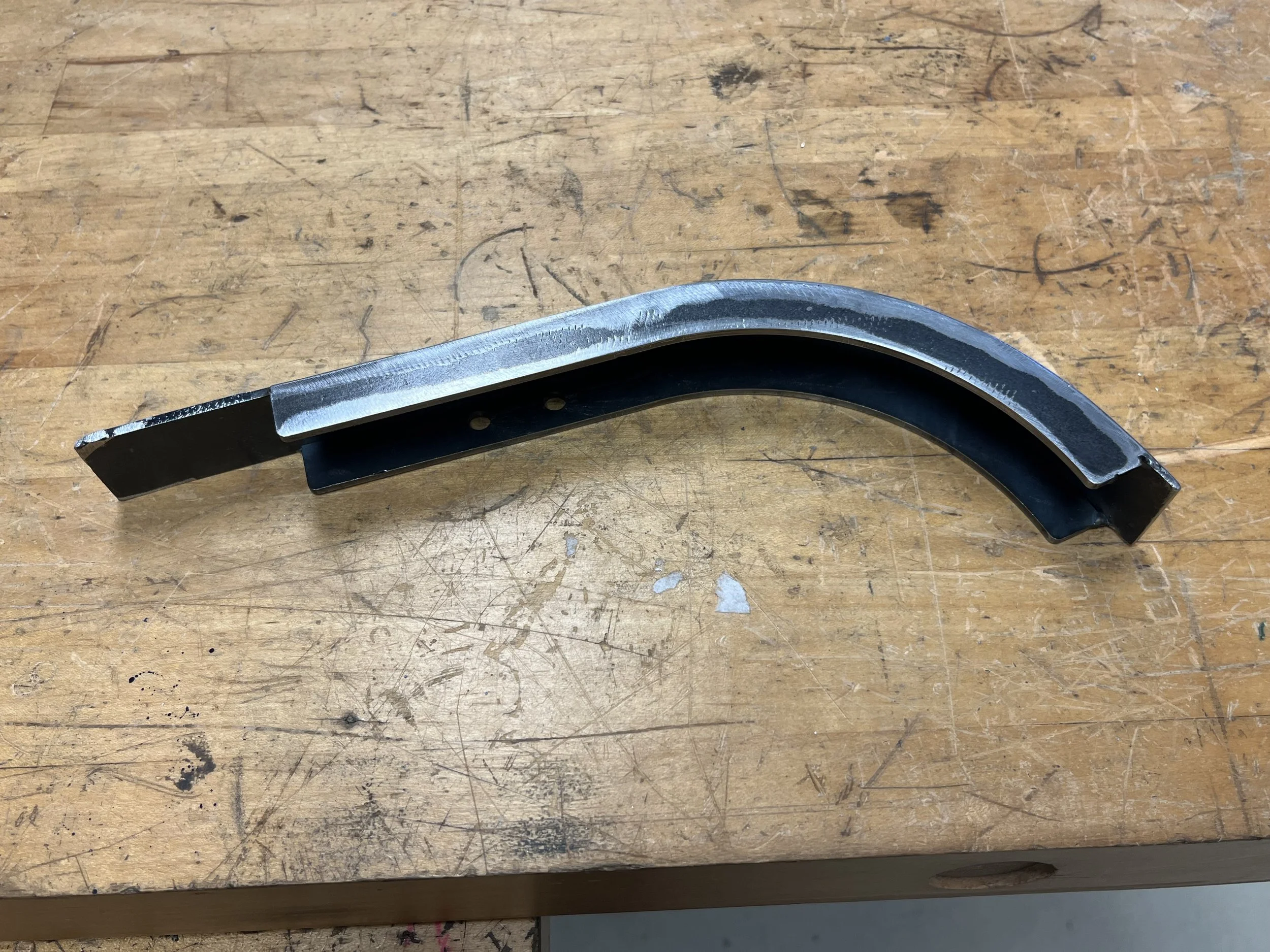
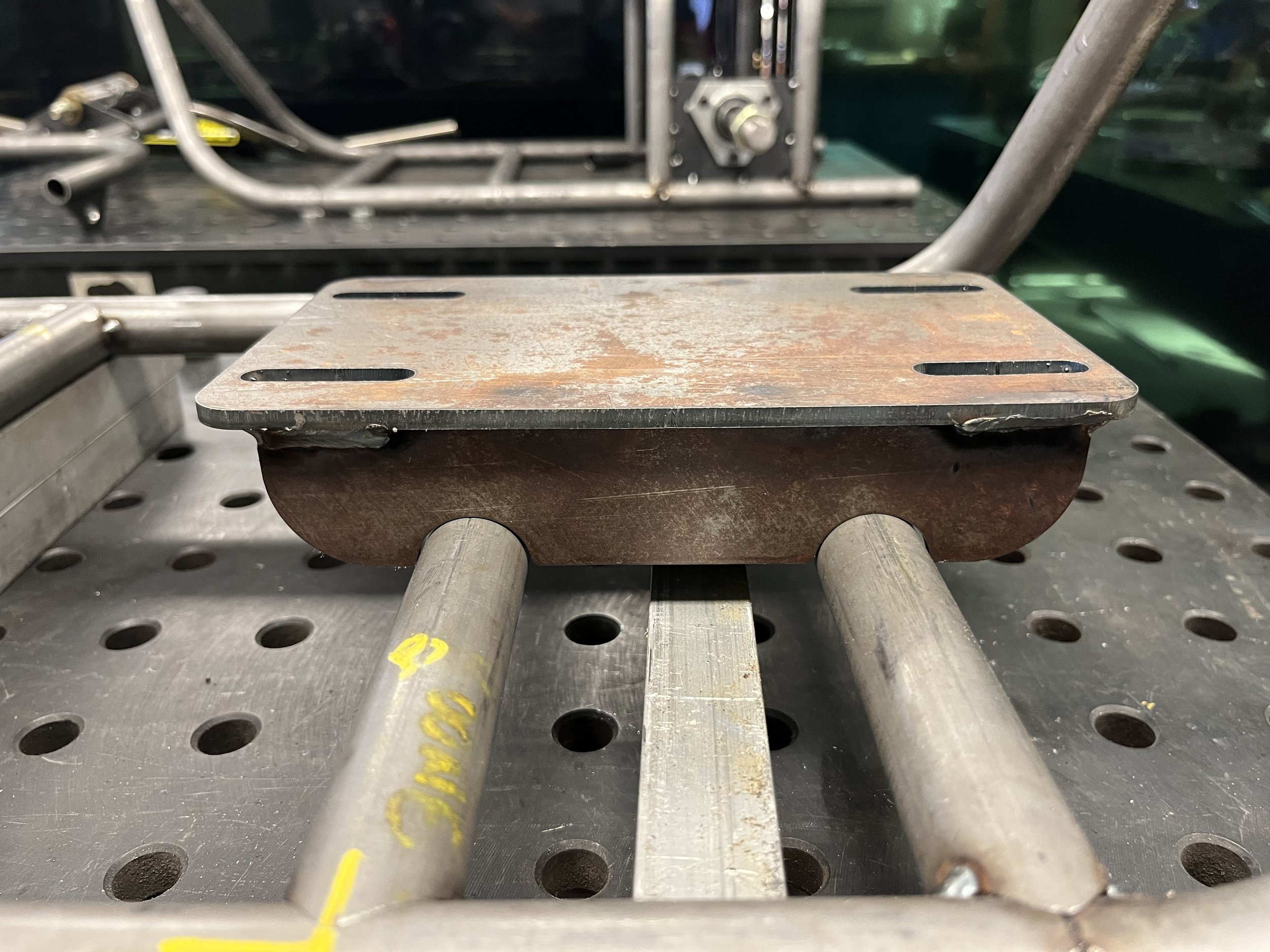
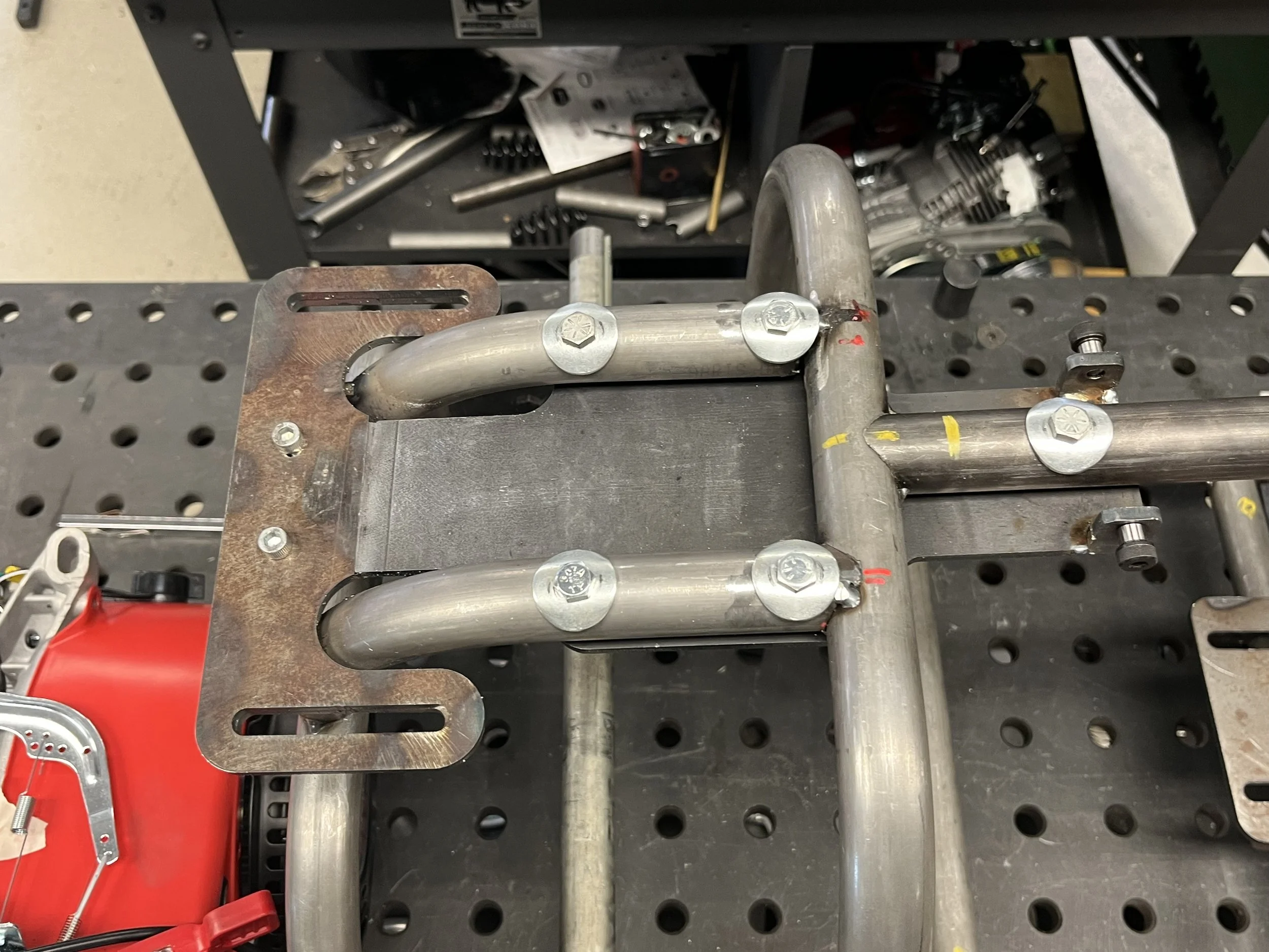
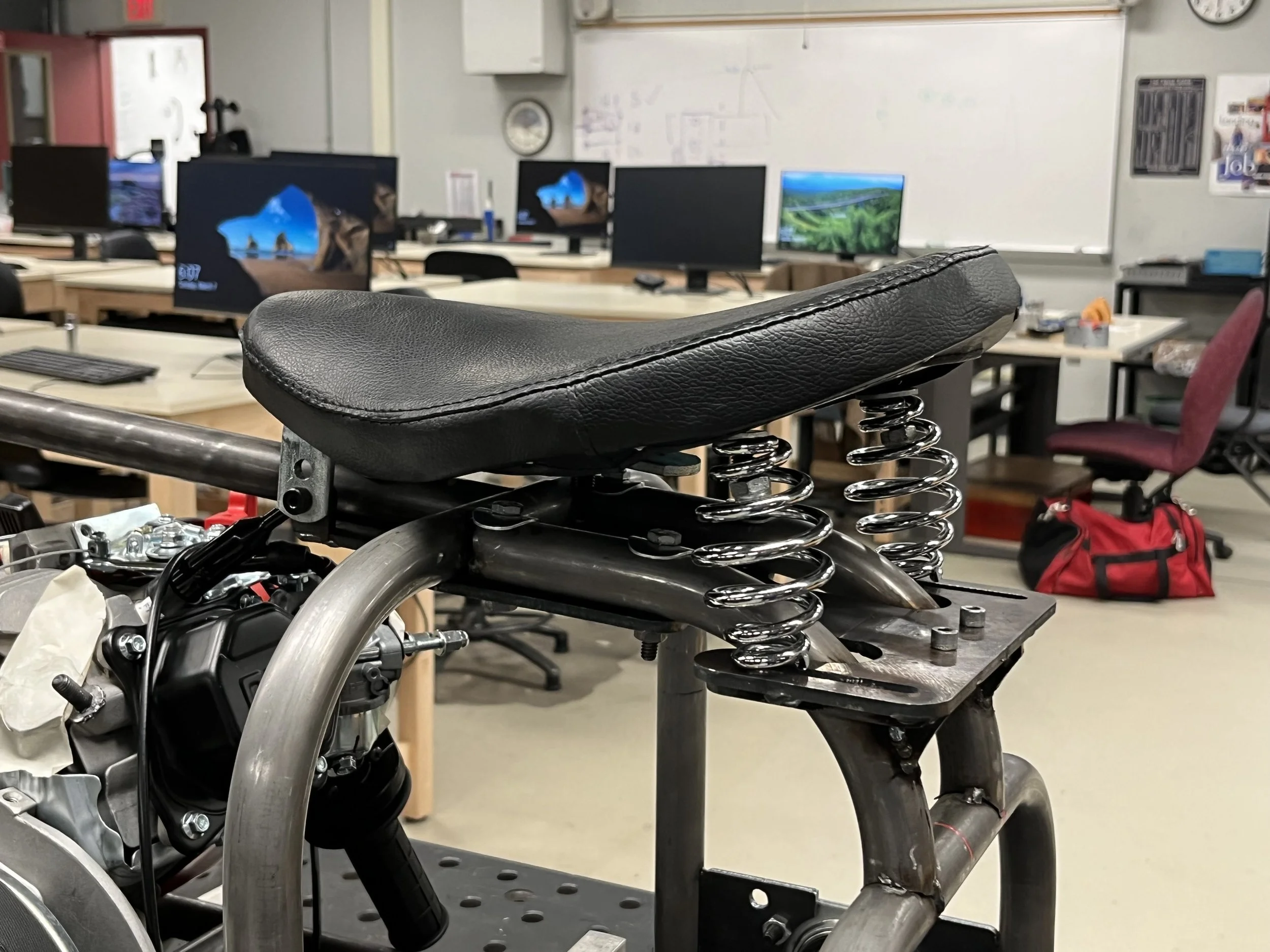
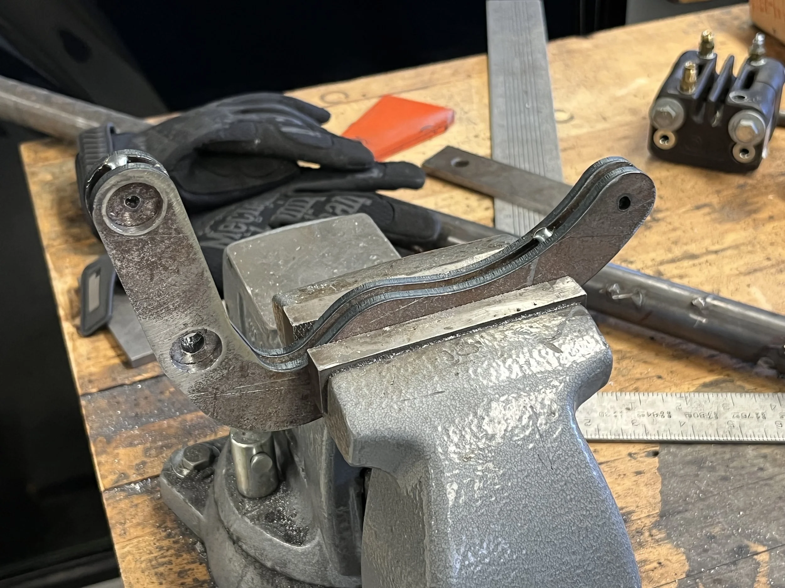
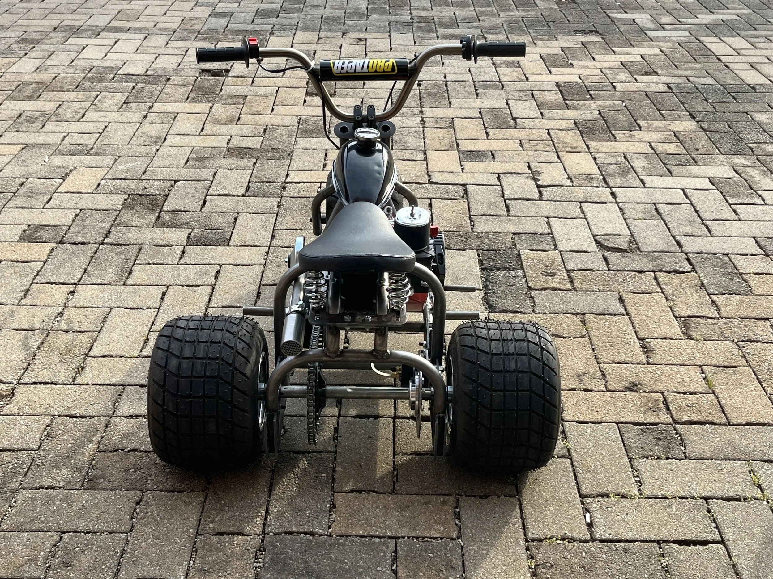
Since our team is about 2 weeks ahead of schedule I spent quite a bit of time re-designing our seat base. Last week we noticed that the trike was very tail heavy when we were ridding it. At times the rider lost control of the trike due to lack of steering control. The design change involved moving the seat base forward 2.5 inches and making the seat bracket adjustable. Due to our laser cutter only cutting up to 3/16 thick material, I doubled up the adjustable bracket to avoid bending it if the seat is set in its most forward position. I spent time at hardware stores looking for certain hardware for the attachment of the springs, and took down the dimensions of the muffler bracket to model it in Solidworks and laser cut it next week. We will be using it to make a custom exhaust for the trike.
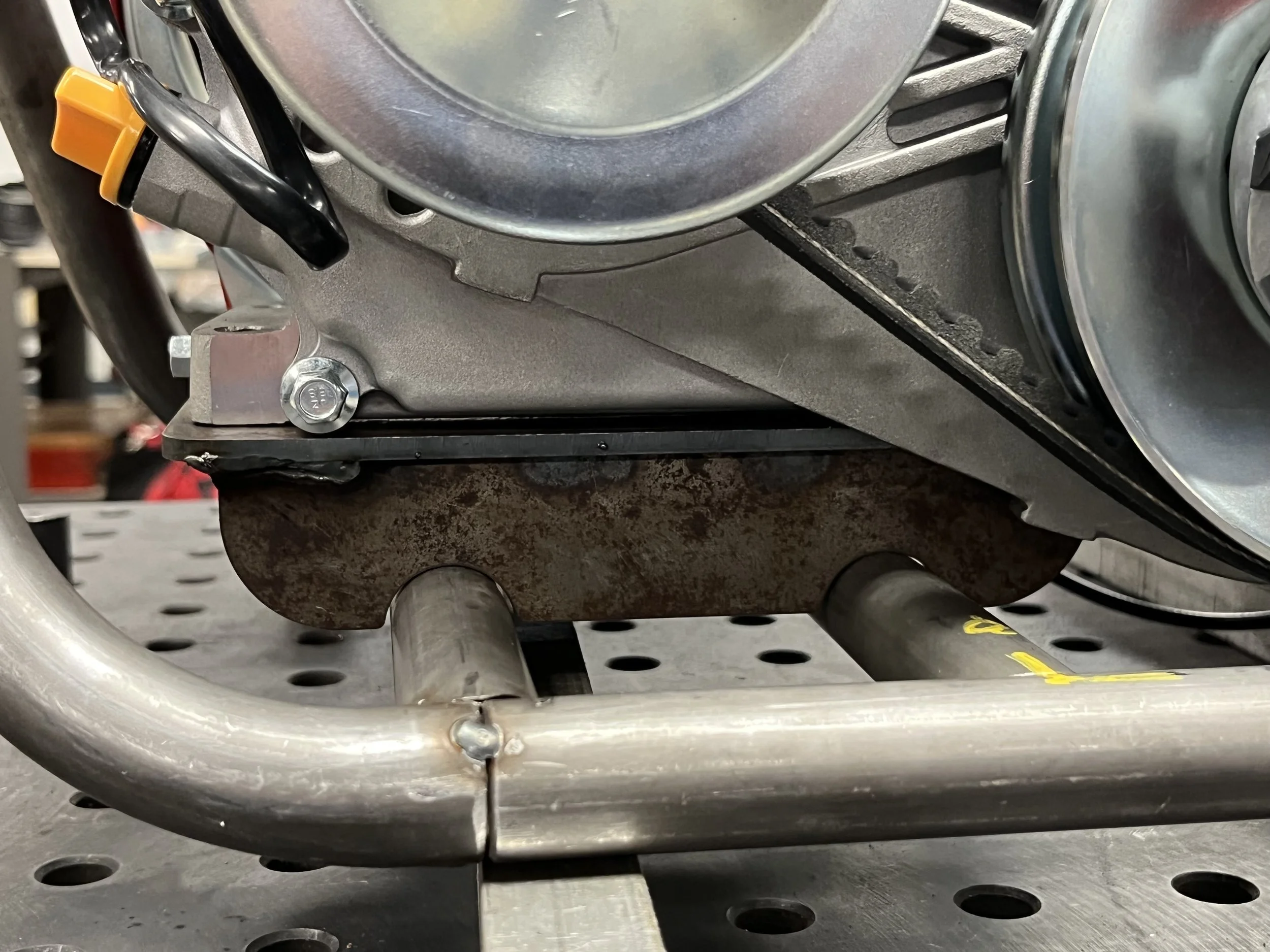
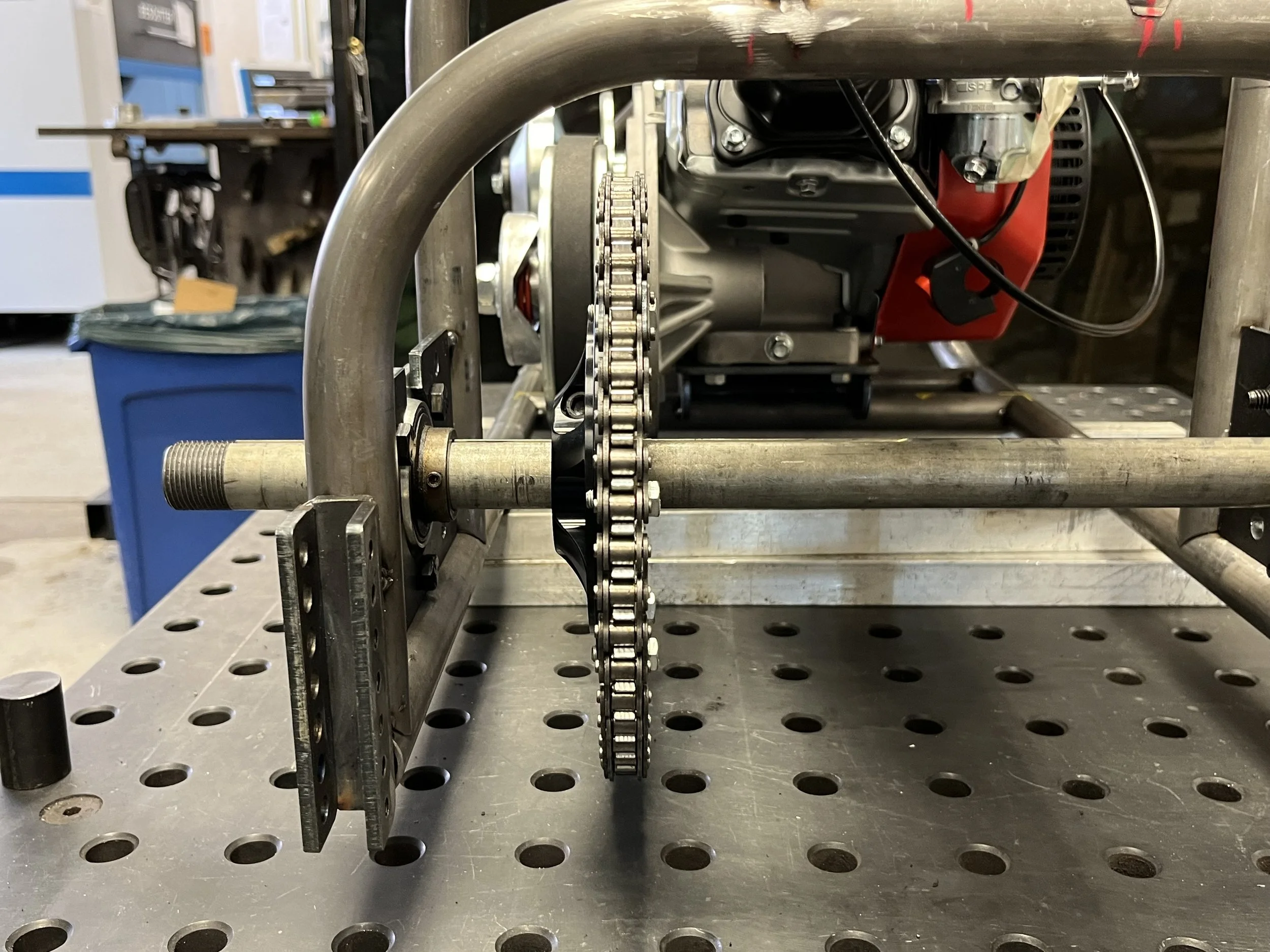
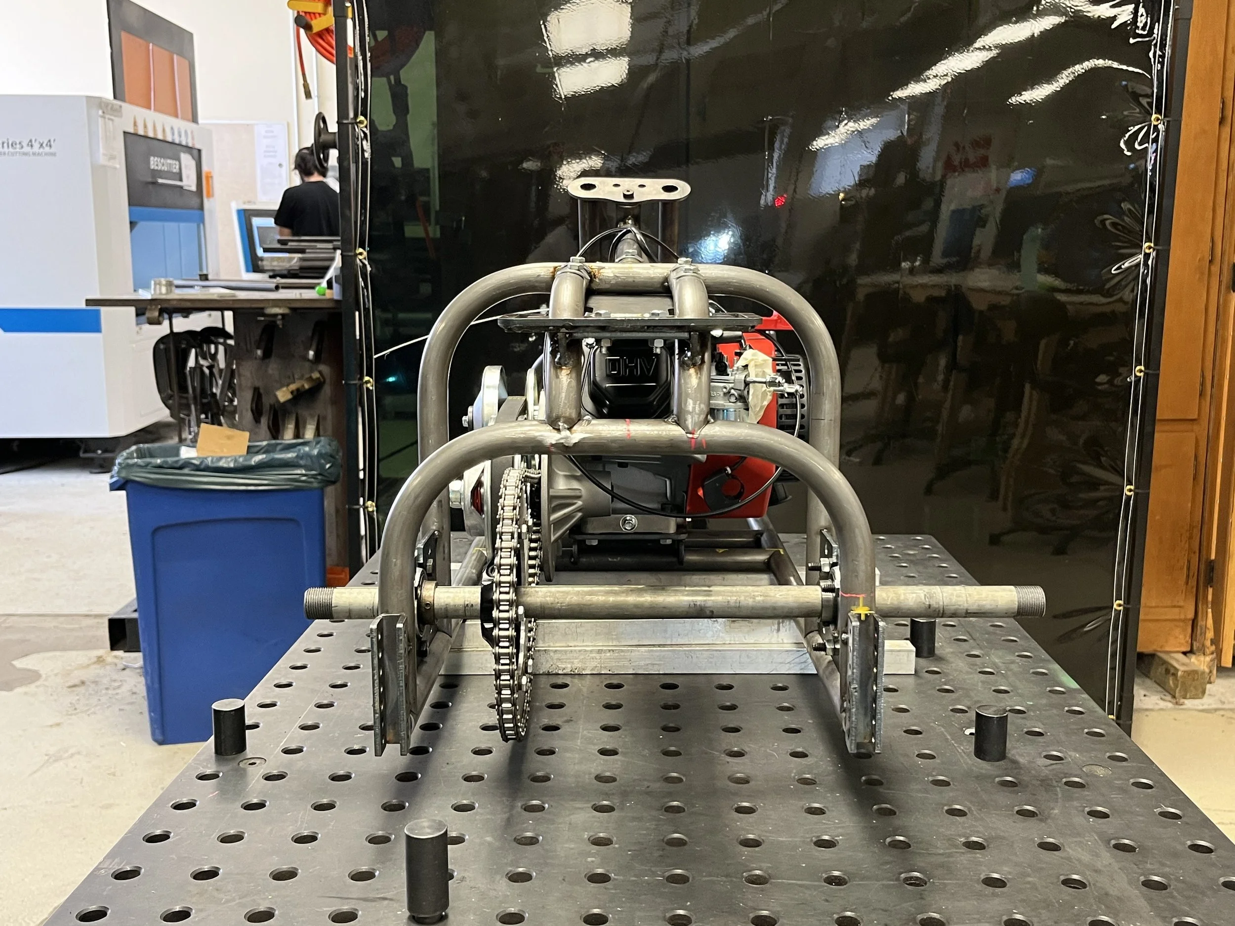
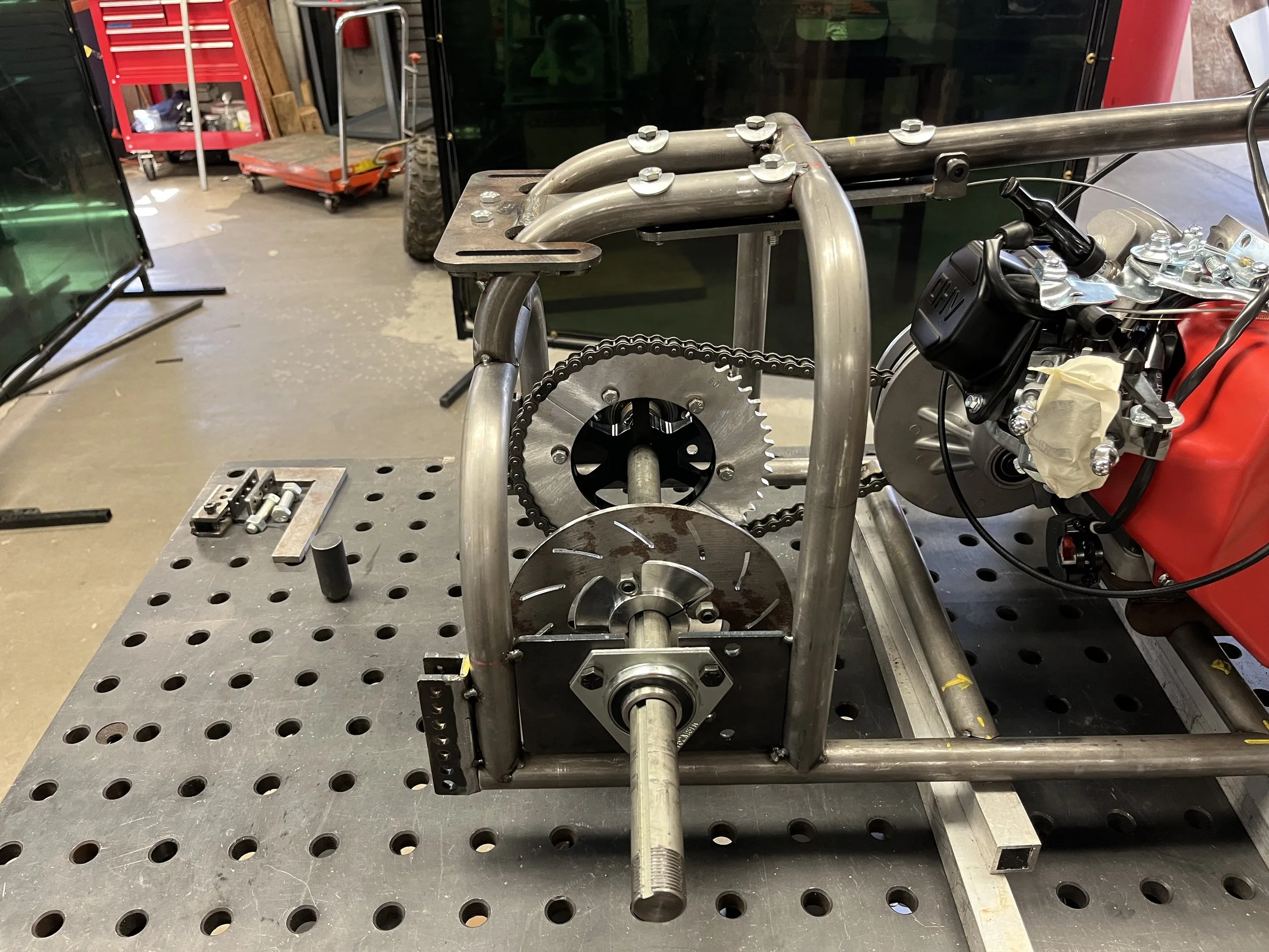
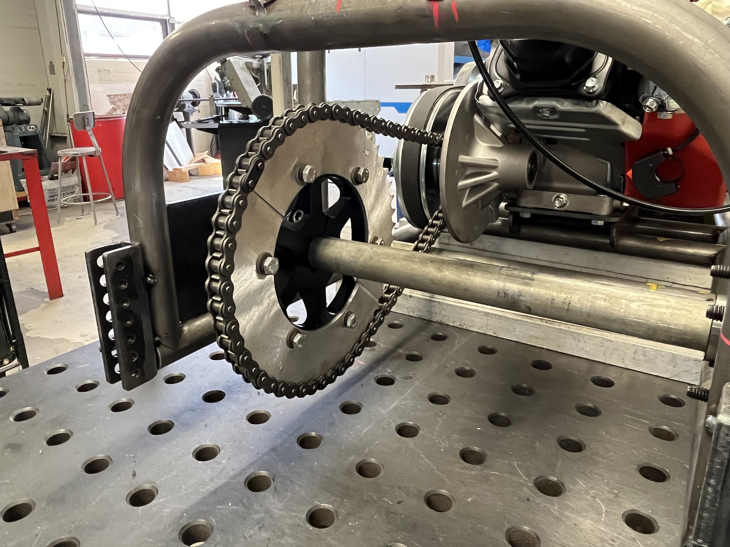
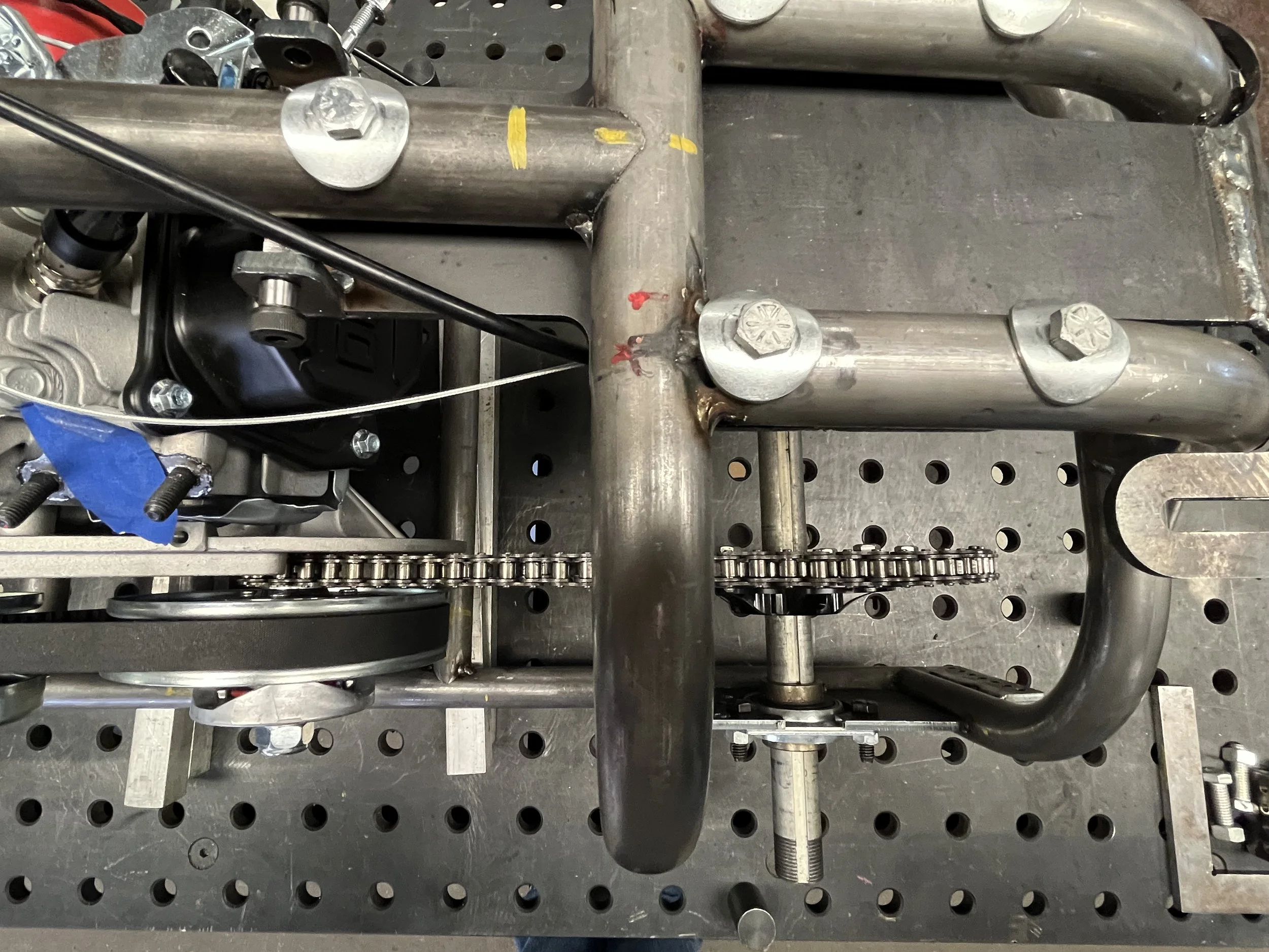
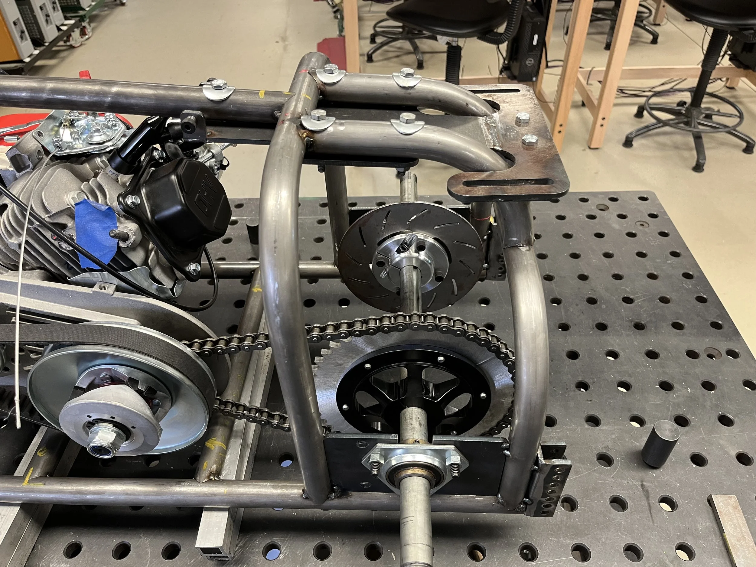
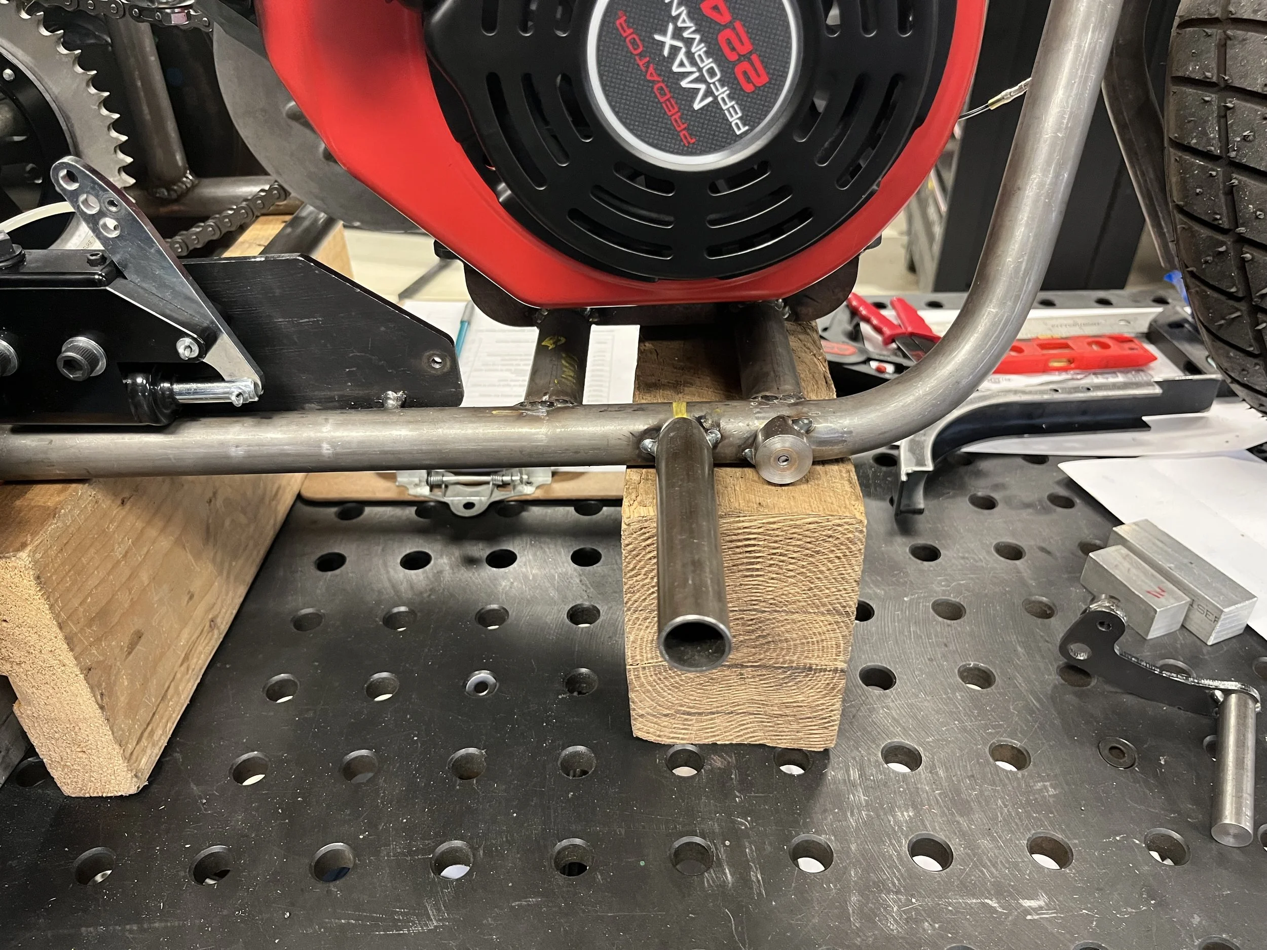
After installing the CVT we encountered clearance issues. Due to the angle of the CVT we no longer had the minimum 3” clearance that the project required. I will be redesigning the engine plate by raising it 1 inch to correct this issue.
Week Six of the Build
Week Seven of the Build
Week Eight of the Build
Week Nine of the Build
Week Ten of the Build
Week Eleven of the Build